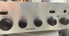
HI,GALU,How to adjust the rear position is 0mV, and the four are the same zero. When it is adjusted to the maximum or zero MV,
Hi, Jacky! I understand you are a beginner and still learning to read circuit diagrams.
I also understand you are based in China so there may be communication problems.
Are you saying that all the measurement suggestions we have made result in readings of zero volts?
Let's try this: Look at the schematic, measure the voltage between the left hand side of C37 and ground and then report back your reading.
I also understand you are based in China so there may be communication problems.
Are you saying that all the measurement suggestions we have made result in readings of zero volts?

Let's try this: Look at the schematic, measure the voltage between the left hand side of C37 and ground and then report back your reading.
I really want to make this machine more powerful


 You can't make "more powerful" by changing bias.


The "4V-5V" point is NOT critical and won't get you more power.
It is what it is.
Hello, his power supply voltage is DC voltage 50V, not 44V. Fine tuning R60 and R61 is 12mv. Is it a little small? Thank you, Adason,Thanks, adason.
I believe the single rail supply voltage is around 44 V dc.
R48 = 330 k and R47 = 33 k
This suggests that the voltage across R47 should be one tenth of the supply voltage, i.e. 4 V, with RP1 providing the fine adjustment.
Am I talking sense, and do you think that is what jacky-bb is referring to when he mentions 4 V - 6 Vdc?
Hello, galU, I'm glad to see this information. I happen to have a first generation Rogers ravensbrook these days. The sound is often distorted sometimes, but occasionally, not often. After I get it these days, I'll measure it. Then I'll put up the picture for you to see. I want to ask you how to make the 6-8 ohm loudspeaker on the load. I want to make one myself. I think it shouldn't be difficult. Thank you,Adason and I were in agreement that 12mV across emitter resistors R60 and R61 sounds OK.
Adason 和我一致认为,发射极电阻 R60 和 R61 上的 12mV 响不错。
hi ,galu, 🙂 The voltage R60 and R61 at both ends of the resistor on the emitter is 12mv. There is nothing wrong with the fine adjustment of RP3 and RP4, but the voltage at both ends of R47 is 2.852v DC. There is no way to adjust RP1 to 5V. Try to adjust the capacitor next to it. C32 voltage can be adjusted to 1.3V, and both sides can be adjusted and balanced. Do you see whether this method is right or not,Adason and I were in agreement that 12mV across emitter resistors R60 and R61 sounds OK.
Attachments
Please measure the voltage between the positive end of capacitor C37 and circuit ground - as I asked you to do back in post #22.
Also, read post #23 - the 5V measurement is not critical.
In that case, your 2.9V measurement should be OK.
In that case, your 2.9V measurement should be OK.
Yes, because there is a coupling capacitor in front, 2.9v is very good, and the two channels are balanced, galUAlso, read post #23 - the 5V measurement is not critical.
In that case, your 2.9V measurement should be OK.
- Home
- Amplifiers
- Solid State
- Rogers Ravensbrook tuner
