Hello, I have a rogersravensbrook tuner amplifier. I need help. I want to debug its bias and standby current. Is it 12mv? Can you provide me with a schematic diagram? thank you,🙂
Attachments
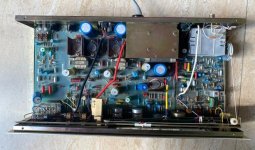

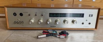
The two resistors are adjustable. I adjust them to DC 5V. I don't know whether it is OK, because there is no circuit diagram. The power of this should be 20W per channel, and the standby current should be about 30mA,
 Who can help me see his principle? Thank you,
I contributed to the following thread on biasing the Ravensbrook amplifier:
https://www.diyaudio.com/community/threads/rogers-ravensbrook-stereo.349181/
I estimated the bias voltage to be 12 mV, and the OP said that worked fine.
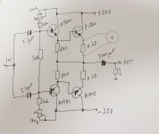
I'll append the amplifier schematic here for reference.
https://www.diyaudio.com/community/threads/rogers-ravensbrook-stereo.349181/
I estimated the bias voltage to be 12 mV, and the OP said that worked fine.
I'll append the amplifier schematic here for reference.
Attachments

I contributed to the following thread on biasing the Ravensbrook amplifier:
https://www.diyaudio.com/community/threads/rogers-ravensbrook-stereo.349181/
I estimated the bias voltage to be 12 mV, and the OP said that worked fine.
I'll append the amplifier schematic here for reference.
 The back four trimming resistors should be 4MV, but the front two (two behind one tube) should not be 4MV DC voltage. I think it should be 4v-6v DC voltage. I really want to make this machine more powerful. I hope that can help me. Give me some advice. Thank you,🙂
The back four trimming resistors should be 4MV, but the front two (two behind one tube) should not be 4MV DC voltage. I think it should be 4v-6v DC voltage.
I'd be interested to know where you got the 4 mV figure from.
Here's the output transistor biasing method as outlined in the Ravensbrook amp thread to which I linked earlier:
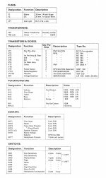
"There are four bias setting preset resistors, two times RP3/RP4, one for each output transistor.
Set the bias to, say, 12mv (I can't find the exact figure) across each 0.47 ohm emitter resistor by adjusting each RP3/RP4 pair."
The "front two" presets to which you refer are designated RP1 on the schematic. Unfortunately, I don't have any information on the procedure for adjusting them. Across which component in the schematic are you expecting to measure 4 - 6 V dc? R47?
Thats not output stage bias. Trimmers rp2 and rp3 are, and should be set to eliminate crossover distortion.
12mV across 0.47 ohm resistor sounds about right.
Not sure what rp1 is adjusting, its a pre for a driver, and its all cap coupled. So it does not affects dc in output.
12mV across 0.47 ohm resistor sounds about right.
Not sure what rp1 is adjusting, its a pre for a driver, and its all cap coupled. So it does not affects dc in output.
Thanks, adason.
I believe the single rail supply voltage is around 44 V dc.
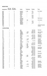
R48 = 330 k and R47 = 33 k
This suggests that the voltage across R47 should be one tenth of the supply voltage, i.e. 4 V, with RP1 providing the fine adjustment.
Am I talking sense, and do you think that is what jacky-bb is referring to when he mentions 4 V - 6 Vdc?
I believe the single rail supply voltage is around 44 V dc.
R48 = 330 k and R47 = 33 k
This suggests that the voltage across R47 should be one tenth of the supply voltage, i.e. 4 V, with RP1 providing the fine adjustment.
Am I talking sense, and do you think that is what jacky-bb is referring to when he mentions 4 V - 6 Vdc?


I was recently working on nice classA buffer, and had no issue to adjust any bias, offcourse distortion was in inverse relationship to the output current
I too used two trimmers, as to adjust each npn and pnp outputs separately, which worked for DC offset, as I used symmetrical supply. I measured bias as voltage drop on the 0.22 ohm output.
But in cap output, with just one assymetrical supply this is less important, still target is about half of the supply voltage on the amp side of the cap.
Attachments
So, the voltage in front of C37 should be 1/2 of the supply voltage.
And, thanks for showing us where to measure the bias voltage. 😎
And, thanks for showing us where to measure the bias voltage. 😎
It seems that the first two adjustments should be DC voltage 4V, and the last four offsets should be 12mv. Is that right,Thats not output stage bias. Trimmers rp2 and rp3 are, and should be set to eliminate crossover distortion.
12mV across 0.47 ohm resistor sounds about right.
Not sure what rp1 is adjusting, its a pre for a driver, and its all cap coupled. So it does not affects dc in output.
The two front should be DC voltage 4V, and the last four fine adjustments should be 12mv,Thanks, adason.
I believe the single rail supply voltage is around 44 V dc.
R48 = 330 k and R47 = 33 k
This suggests that the voltage across R47 should be one tenth of the supply voltage, i.e. 4 V, with RP1 providing the fine adjustment.
Am I talking sense, and do you think that is what jacky-bb is referring to when he mentions 4 V - 6 Vdc?
By the "two front", he means the two RP1 trimmers and refers to my post #10 in relation to the 4 V.
“两个前面”是指两个 RP1 修剪器,指的是我的帖子 #10 与 4 V 相关
yesBy the "two front", he means the two RP1 trimmers and refers to my post #10 in relation to the 4 V.
- Home
- Amplifiers
- Solid State
- Rogers Ravensbrook tuner