Hello -
As I mentioned in my previous thread, I recently dug my Rogers LS4a's out of storage and have begun to investigate restoring them.
I will preface this post by saying I am definitely a novice, but I do try to research things thoroughly before moving forward or reaching out for help.
One of the speakers works fine. The other has a blown tweeter. In my previous thread I requested help with locating replacement tweeters for them. Forum member @vinylkid58 kindly pointed me in the direction of Solen that has them in stock. Before pulling the trigger, I decided to investigate further to see if I could find the reason that the one tweeter blew in the first place. I never abused them.
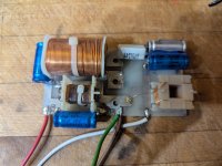
I removed the crossovers and purchased an inexpensive LCR meter (not for accuracy necessarily, but for comparative purposes) to test the caps. The woofer circuit consists of a 40 uF cap and an 8 uF cap. I isolated the caps and the 40's measured 41.2 and 41.3 respectively and the 8's measured 8.3 and 8.4. Acceptable values I believe.
The tweeter circuit is where the situation gets a bit difficult. To make matters more challenging, the cellophane wrapping on one of the caps disintegrated on both boards.
On the working circuit, the caps both measured 8.3 uF. One definitely is 8 uF and I believe that the other cap is also because what was left of the wrapper has a number code that matches the other. On the non-working circuit I do not get a reading for the 8 so that cap is definitely a problem. For the unknown cap, I get a reading of 4.3.
In my research prior to this post, in a very limited sample, I see that Rogers did have a tweeter crossover configuration for the LS4a's that was a 4.7 uF cap along with an 8. It is actually difficult to locate identical crossovers for this speaker - supposedly they had several different configurations. I am pretty confident that the working circuit consists of two 8's. Is it possible that the non-working one is a 4.7 and an 8? Or is it most likely that the 4.3 reading is an 8 uF cap that has failed.
Could a pair of matched speakers actually have different crossover configurations? In a repair video posted on YouTube, the pair being worked on had the same caps but one had an added resistor on the notch filter.
As far as the actual repair is concerned, my goal is to eventually re-cap the entire board. But to begin with, my plan is to recap the bad tweeter circuit and test it with the working speaker I have. I will then repeat the process on the working board so that the two circuits are identical. I saw Solen polypropylene type caps were now the recommended replacement with maybe slightly increasing the resistor. Does this seem accurate? If not, the original AlCap ones seem readily available -- if I can figure out the correct specs.
I am attaching two photos - the first is of my board and the second is of a LS4a crossover I found on the web.
Thanks in advance for any knowledge you all might have to offer.
As I mentioned in my previous thread, I recently dug my Rogers LS4a's out of storage and have begun to investigate restoring them.
I will preface this post by saying I am definitely a novice, but I do try to research things thoroughly before moving forward or reaching out for help.
One of the speakers works fine. The other has a blown tweeter. In my previous thread I requested help with locating replacement tweeters for them. Forum member @vinylkid58 kindly pointed me in the direction of Solen that has them in stock. Before pulling the trigger, I decided to investigate further to see if I could find the reason that the one tweeter blew in the first place. I never abused them.
I removed the crossovers and purchased an inexpensive LCR meter (not for accuracy necessarily, but for comparative purposes) to test the caps. The woofer circuit consists of a 40 uF cap and an 8 uF cap. I isolated the caps and the 40's measured 41.2 and 41.3 respectively and the 8's measured 8.3 and 8.4. Acceptable values I believe.
The tweeter circuit is where the situation gets a bit difficult. To make matters more challenging, the cellophane wrapping on one of the caps disintegrated on both boards.
On the working circuit, the caps both measured 8.3 uF. One definitely is 8 uF and I believe that the other cap is also because what was left of the wrapper has a number code that matches the other. On the non-working circuit I do not get a reading for the 8 so that cap is definitely a problem. For the unknown cap, I get a reading of 4.3.
In my research prior to this post, in a very limited sample, I see that Rogers did have a tweeter crossover configuration for the LS4a's that was a 4.7 uF cap along with an 8. It is actually difficult to locate identical crossovers for this speaker - supposedly they had several different configurations. I am pretty confident that the working circuit consists of two 8's. Is it possible that the non-working one is a 4.7 and an 8? Or is it most likely that the 4.3 reading is an 8 uF cap that has failed.
Could a pair of matched speakers actually have different crossover configurations? In a repair video posted on YouTube, the pair being worked on had the same caps but one had an added resistor on the notch filter.
As far as the actual repair is concerned, my goal is to eventually re-cap the entire board. But to begin with, my plan is to recap the bad tweeter circuit and test it with the working speaker I have. I will then repeat the process on the working board so that the two circuits are identical. I saw Solen polypropylene type caps were now the recommended replacement with maybe slightly increasing the resistor. Does this seem accurate? If not, the original AlCap ones seem readily available -- if I can figure out the correct specs.
I am attaching two photos - the first is of my board and the second is of a LS4a crossover I found on the web.
Thanks in advance for any knowledge you all might have to offer.
Attachments

It's unlikely they were different out of the factory, but these speakers may have an untold repair or modification history. It's sensible to try to return them to standard unless you have much bigger plans for them. Given the troubles and the age, I'd replace both sides evenly if possible.
In addition it may help to have the tweeter circuit to refer to. Have you considered drawing it before you begin...
In addition it may help to have the tweeter circuit to refer to. Have you considered drawing it before you begin...
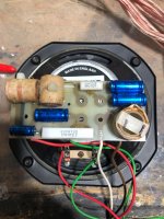
Looking at your Xover it is for a non biwire version, the web based find is for a bi wireable version.
Possibly it has a slightly different Xover due to a production or drive unit change.
Also worth noting that your inductors are air cored as far as I can see, whilst the others are ferrite cored or some such. Which may mean they have differing DCR resistance values. To measure what you have with your LCR means you probably have to lift one of the component legs to remove the rest of the circuits influence and then measure it. It would be nice to draw out the circuit diagram or find it on the web to use as a reference.
Looking at your Xover it is for a non biwire version, the web based find is for a bi wireable version.
Photos show that the LS4a has a single pair of terminals whilst the LS4a/2 has two pairs of terminals.
The picture of the crossover taken from the web pertains to the LS4a/2.
Hello again -
Thank you for the replies.
The speakers are as they were from the factory. I was the original buyer and once the tweeter had issues, I put them away with the intention of someday figuring out what the issue is. A few decades later, here we are!
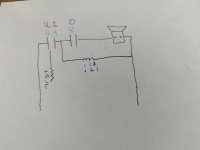
I attached a very primitive drawing of the tweeter circuit along with the recorded values. Go easy - as I mentioned this is my first attempt at anything speaker related. I have no idea where the 1.5 Ohm resistor belongs. It seems to jump between the tweeter and woofer circuit.
The inductors on both crossovers measure .21 mH.
Ah, that explains the bi-wire/non bi-wire versions.
I think best course of action at the moment based on my expertise (or lack thereof) is to swap the two 8 uF caps and the resistor on both crossovers. I'll then check that they work with the one good tweeter I have. If I am successful, I'll explore doing the same to the woofer circuit.
A few questions:
So it is logical that both crossovers would have been spec'd the same from the factory? The 4.2 reading that I am getting on the one cap is probably degradation?
Should I seek out ALCap capacitors to keep them original? Or, are there better ones nowadays that you would recommend?
Thanks again.
Thank you for the replies.
The speakers are as they were from the factory. I was the original buyer and once the tweeter had issues, I put them away with the intention of someday figuring out what the issue is. A few decades later, here we are!
I attached a very primitive drawing of the tweeter circuit along with the recorded values. Go easy - as I mentioned this is my first attempt at anything speaker related. I have no idea where the 1.5 Ohm resistor belongs. It seems to jump between the tweeter and woofer circuit.
The inductors on both crossovers measure .21 mH.
Ah, that explains the bi-wire/non bi-wire versions.
I think best course of action at the moment based on my expertise (or lack thereof) is to swap the two 8 uF caps and the resistor on both crossovers. I'll then check that they work with the one good tweeter I have. If I am successful, I'll explore doing the same to the woofer circuit.
A few questions:
So it is logical that both crossovers would have been spec'd the same from the factory? The 4.2 reading that I am getting on the one cap is probably degradation?
Should I seek out ALCap capacitors to keep them original? Or, are there better ones nowadays that you would recommend?
Thanks again.
Attachments
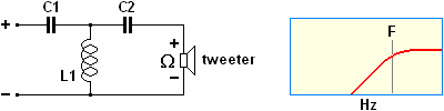
The two capacitors and single inductor would indicate a 3rd order high pass filter as shown attached.
I would think that both crossovers would contain identical components
By all means use Alcaps for originality. Alternatives that we use over here are the German made Mundorf E-Cap capacitors.
I would think that both crossovers would contain identical components
By all means use Alcaps for originality. Alternatives that we use over here are the German made Mundorf E-Cap capacitors.
Attachments
I think it is safe to assume that both Xovers would be the same. Consequently the 4uf value you are measuring for the failed one means it hasn't aged as well as the others.
If you liked the sound before they went into storage some modern Mundorf Bi Polars would be a safe bet compared to just going straight to low loss plastic types. If you want capacitors from the original manufacturer I believe Falcon acoustics can help with these.
If you liked the sound before they went into storage some modern Mundorf Bi Polars would be a safe bet compared to just going straight to low loss plastic types. If you want capacitors from the original manufacturer I believe Falcon acoustics can help with these.
I have no idea where the 1.5 Ohm resistor belongs. It seems to jump between the tweeter and woofer circuit.
It may be that the 1.5 ohm is a tweeter attenuating resistor. If so, it would be in series with the left hand capacitor (C1 in my attachment).
Have another look at the circuit to see if this is, in fact, the case. EDIT: It appears so to me.
Here's a link to Falcon Acoustics' three-strong Alcap capacitor range as mentioned by raymondj:
https://www.falconacoustics.co.uk/l.../alcap-claritycap-solen-audio-capacitors.html
Last edited:
The 4.2 reading that I am getting on the one cap is probably degradation?
It would appear from the evidence presented that C1 is 4.0 uF and C2 is 8.0 uF.
So 4.2 uF is a correct reading for C1.
EDIT: I've just checked on a 3rd order HP crossover calculator and C1 = 4 uF, C2 = 8 uF and L1 = 0.21 mH would be consistent with the requirements of the LS4a's HP filter.
Last edited:
The 1.5 ohm is in series with the left hand capacitor as you describe. I am just confused by the second solder point connecting it to the woofer inductor (attached).
Is it likely that something caused a catastrophic failure of the capacitors and sound coil at the same time?
I think I'll keep them original only for the sake of knowing I'm swapping like for like. If this project turns out to be a success, I might explore other options. They sounded excellent to my youthful ears and budget at the time!
Thanks for the Falcon link. The 8 uf caps are low loss. Does it matter? Falcon does not have those but I located them at HiFi collective.
I assume there is no real difference between brands of resistors?
Thanks again for the info and patience.
Attachments

I'm getting reading of 0 for C2 - that's not the non-working board. On the working one, both caps read 8 uF.It would appear from the evidence presented that C1 is 4.0 uF and C2 is 8.0 uF.
So 4.2 uF is a correct reading for C1.
EDIT: I've just checked on a 3rd order HP crossover calculator and C1 = 4 uF, C2 = 8 uF and L = 0.21 mH would be consistent with the requirenents of the LS4a's high pass crossover.
The 8 uf caps are low loss. Does it matter?
LL caps have less 'series resistance' than standard 50 V Alcaps so can make a tweeter sound a tad brighter. However, I wouldn't agonise over it!
I assume there is no real difference between brands of resistors?
To me, a resistor is a resistor when it comes to audio frequency loudspeaker crossovers. Consequently, I submit there is no need to go for an 'exotic' brand.
P.S. I would experiment with the value of C1 and see how the sound pans out.
P.P.S. First sentence edited!
Last edited:
The 8's all have an "LL" designation, the 40 does not.
So I should experiment with a 4 uF cap at C1 and see? Would you do that on both boards? Basically, try both a 4 and an 8 and go with the one I prefer. To o confirm, the boards should be identical in the end. No reason to go with a 4 on one and an 8 on the other.
So I should experiment with a 4 uF cap at C1 and see? Would you do that on both boards? Basically, try both a 4 and an 8 and go with the one I prefer. To o confirm, the boards should be identical in the end. No reason to go with a 4 on one and an 8 on the other.
I hope you noticed I edited my previous post.
The bass filter would not benefit from LL capacitors in the way that the tweeter filter would.
Yes, try either 4 & 8 or 8 & 8. The same combination on both boards, but not a mixture of the two.
The bass filter would not benefit from LL capacitors in the way that the tweeter filter would.
Yes, try either 4 & 8 or 8 & 8. The same combination on both boards, but not a mixture of the two.
There's some confusion. The first photo is of my crossover, the non-biamping one. The second photo, as I mentioned, is one that I found on the web. I was curious as to why the same speaker model had several different crossover configurations. It was explained above that there was also was a model LS4a/2 that was the biamp version.
My working speaker has two 8 uF caps on the tweeter circuit. The non-working one's measure 4.2 uF and 0. That seems unlikely to be a factory configuration. I assume that they were once both 8's and either degraded or were damaged. As discussed above, it is possible that the C1 is a cap in the 4 uF range, but the C2 still has its wrapper intact and that is definitely an 8.
In a video on YouTube, the crossovers were also different -- one having an added resistor. The guy doing the repair mentioned that Rogers was known to tweak their speakers to match before leaving the factory.
for biamping mode
Passive biampimg. Serious biamping requires the XO before the amps, not after.
dave
- Home
- Loudspeakers
- Multi-Way
- Rogers LS4a Crossover Rebuild Assistance Needed