Hi everyone, I had a schematic for the intergrated amp, but lost it as my old laptop failed, I did notice some differences about the circuit as to the 2 part version. Does anybody have a copy they could forward to me, I down loaded it from the net years ago, but unable to find it again, I would be most grateful if someone could help
You'll find a couple of schematics here: http://ukhhsoc.torrens.org/makers/Rogers/CADETMk3/index.html
I don't know of the differences you mention.
I don't know of the differences you mention.
Last edited:
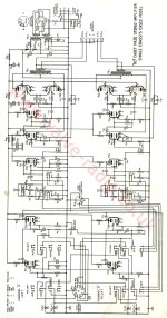
Thank you for the schematic, I think you may be right, it may be some of the component values ? I saw in a earlier question (years ago) about the small cap across pins 6 & 9 on the valve of the 2 part unit, I had one of these and some of the component values were different on that, may be some updated mods, any way, thanks again, Paul

Hi Galu, you sent me the 1 part cadet 3 schematic. My reply stated small cap on the valve base, it was pins 6 + 8, not 6 + 9, if you search "rogers cadet schematics corrections" there is a schematic showing this cap, if you google "rogers cadet images" some of the images show this cap
Thanks Paul, I've found this thread: https://www.diyaudio.com/community/threads/rogers-cadet-iii-schematics-corrections.94746/
However, in post #3 of that thread, the OP says his first post is mistaken and that the modified schematic (attached) is correct.
The schematic came from this earlier thread and was verified by Planet10: https://www.diyaudio.com/community/threads/rogers-cadet-iii-schematics.45796/
Perhaps this will clarify things?
Attachments
you'll also find it somewhere on (k)Curt Lilienthal's site backup
https://fr.scribd.com/document/582445842/100-Amplifiers-part-2-1945-54-Lilienthal-Engineering#
https://fr.scribd.com/document/582445842/100-Amplifiers-part-2-1945-54-Lilienthal-Engineering#
Thanks Paul, I've found this thread
My drawing, i would have been cleaning up someone else’s mess.
dave
Last edited:
I've just found the thread of this mystery capacitor, it was not on this site ! It's on "UK Vintage Radio", was posted by "Emibell", titled "mystery capacitor rogers cadet", posted "2nd April 2016", and is still viewable on the thread search if anyone wishes to look.
- Home
- Amplifiers
- Tubes / Valves
- Rogers Cadet 3 intergrated schematic