Well I think now I’m more clear about heating up the source is to say that the part that gets a little warmed up is the one that handles the output voltage and the low voltage and the other transformer only handles voltage to the outputs I think he was running around with something that’s normal. I confirm that the signals are good and the voltages in the output stage regulators are correct, the problem is when I install the outputs starts flashing the flashing yellow led and very faint is to say that I have a problem with the exit stage since without the output fet the same does not blink
Did you check the drive signals at the outputs with the output FETs in the circuit and the rectifiers out of the circuit?
With the output FETs in the circuit I don't get a signal
Is the amp trying to draw excessive current when powering up?
The amplifier only extracts 3.2 amp
Is there any pulsing DC on the speaker terminals when the amp tries to power up?
There is no DC in the speaker terminals.
In short I have problems with the BD output card
Attachments
Didn't you check the output drive signals and all were OK?
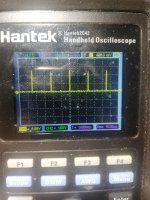
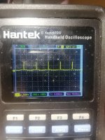
Antes no las revisé debido a que una vez retiré los FET el amplificador dejó de parpadear el led amarillo, me enfoqué en la fuente por el calentamiento de los mosfet de un transformador. La señal hasta los rectificadores es una buena ola cuadrada
How do you know for certain that the driver board is the problem?
* I do not know for sure I assume she is because I have no signal in the FET, nor any signal coming out of the card, is there any way to test the driver board outside the circuit, I checked the resistor diodes and transistors close to the FET voltages of the regulators and all are ok
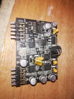
* What else should I check this amplifier comes from another workshop that could not give the same solution if you have any image of the driver board would be great since I see that they replaced two TL072 circuits
I apologize for my English, I use a translator to understand what you say and convey my doubts, maybe that's why I don't explain myself well
Did you check the drive signals at the outputs with the output FETs in the circuit and the rectifiers out of the circuit?
Correct I have already done this test and I don't get a signal in the FET.
It's rare to have absolutely no square wave signals on the header for the driver board. Are you saying that there was no signal other than the DC supply voltages feeding the board?
It's easiest to test these boards using the Arduino type breadboard jumpers.
It's easiest to test these boards using the Arduino type breadboard jumpers.
Attachments
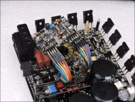
You have to have the driver board in the circuit to have any square waves outside the power supply.
If you don't have any jumpers like those in the photo (available for dirt-cheap, or cheaper on ebay), make some from ribbon or other small wire so you don't have to keep removing the board.
If you don't have any jumpers like those in the photo (available for dirt-cheap, or cheaper on ebay), make some from ribbon or other small wire so you don't have to keep removing the board.
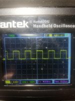
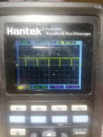
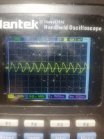
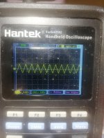
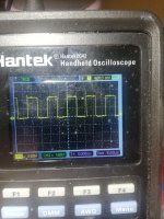
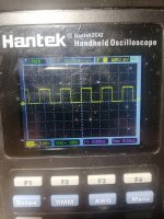
good night Perry these are the signals I get on the circuits
the signals that are square are from the U2000 and the others are from the U2002
the signals that are square are from the U2000 and the others are from the U2002
Attachments
- Status
- This old topic is closed. If you want to reopen this topic, contact a moderator using the "Report Post" button.
- Home
- General Interest
- Car Audio
- Rockford T2500 - 1BD