The voltage driving the gates should be positive relative to the source, and exceeding 5V. So I think there might be something wrong with the gate drive...
rechecked em; they didnt look much different. q208/q209 seem lower than the rest; i think i'm going to investigate that and or wait until perry posts up waveforms from his
Rockford
This is a grounded bridge design - be carefull.
It is impossible to remove the bad MOSFETs and sweat on new ones unless you have the equipment.
We remove the bad FETs, and use grease on the replacements and then use clamping bars using the substrate's mounting holes to clamp the bar
This is a grounded bridge design - be carefull.
It is impossible to remove the bad MOSFETs and sweat on new ones unless you have the equipment.
We remove the bad FETs, and use grease on the replacements and then use clamping bars using the substrate's mounting holes to clamp the bar
These are the drive signals from a working amp (all original) with the outputs IN the circuit. I didn't have to do anything to the output stage so I didn't take them out of the circuit.
This was done with a differential probe setup (two probes per FET) so the polarity may be different than if they were taken with a normal setup (which really wasn't practical with the outputs in the circuit).
I've never had to check this before on one of these amps so it's a bit surprising to see such a difference in the drive signals. It's also surprising to see how far from square they are. Yours should be more square since no outputs are in the circuit.
place the cursor over the thumbnail to see which transistor they are from.
Attachments
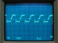
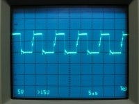
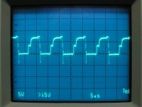
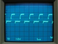
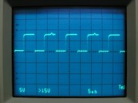
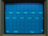
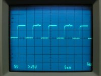
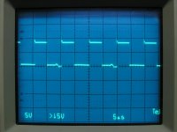
yea i had it on add, ch1 on gate, ch2 on source (right most pin correct?), set to add 2nd channel inverted. Aside from bandwidth limiting i think i had my scope set the same; i'm not sure what that means or if my scope can do it but here's what i got:
Q211/Q214

Q213/Q212

Q208/Q209

Q207/Q210

heres the face of my scope for referance:

Q211/Q214
Q213/Q212
Q208/Q209
Q207/Q210
heres the face of my scope for referance:
The long legs wouldn't affect the amplitude of the signal. If the diodes in the drive circuit were defective, it could cause the signal to be weak but I wouldn't expect a clean drive signal with bad diodes. You could remove them and check them relatively easily. Check for leakage (meter on ohms) as well as forward voltage drop (diode check). There may be a tiny bit of reverse leakage. If all leak the same, it's likely normal.
i get a reading of "417" on my multimeter set to diode mode with the negative on the side with the bar and posative on the side with no bar, reverse it so posative is on the end with the bar and it reads 0.
i pulled d207 d208 d210 and used d212 and d11 as referance as they all have the same part number "ED 47A"
i pulled d207 d208 d210 and used d212 and d11 as referance as they all have the same part number "ED 47A"
What does your meter read with open leads?
Diode-check applies a voltage across the leads through an internal resistance. When the probes are connected across a component, the voltage is dragged down to the forward voltage of the component (for semiconductors, when forward biased by the meter). Resistors simply drag it down like you would see for any 2-resistor voltage divider.
You need to get a better meter for repair work. I'd recommend a used (or new if you can find one) Fluke model 10, 11 or 12.
- Status
- This old topic is closed. If you want to reopen this topic, contact a moderator using the "Report Post" button.
- Home
- General Interest
- Car Audio
- Rockford T10001BD blown output fet