hello on rockford P8004 PC-4707B
a rear right speaker output 37.70 volts DC
the others are ok zero volts
powered in 13 volts no-load consumption 1A
i made measurements with a fluke 179 for the power mosfets and the drivers Q426 Q427 Q415 Q416 Q425 Q424
thanks for your help


a rear right speaker output 37.70 volts DC
the others are ok zero volts
powered in 13 volts no-load consumption 1A
i made measurements with a fluke 179 for the power mosfets and the drivers Q426 Q427 Q415 Q416 Q425 Q424
thanks for your help
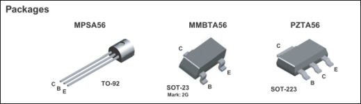
What are the pins (BCE?) top to bottom for the smaller SMD transistors?
If you touch a dummy/speaker load across the 37v on the speaker terminals, does the current draw spike or does it simply drop to near 0v?
If you touch a dummy/speaker load across the 37v on the speaker terminals, does the current draw spike or does it simply drop to near 0v?
hello Perry:
I put a load of 4 ohm the consumption went up to more than 20 amps

I cut, the mosfet Q420 and Q423 were burning I removed them to check them and they are burnt
I checked R463 ok 511 ohm
Q427 B-38.07 volts
C -38.06 volts
E -38.06 volts
I put a load of 4 ohm the consumption went up to more than 20 amps
I cut, the mosfet Q420 and Q423 were burning I removed them to check them and they are burnt
I checked R463 ok 511 ohm
Q427 B-38.07 volts
C -38.06 volts
E -38.06 volts
By 'they are burnt'. do you mean shorted or otherwise defective?
Is this a new problem or did you only recently check them?
Were these previously replaced? They appear original.
Why are you getting different Q427 voltages?
Is Q427 shorted?
Is this a new problem or did you only recently check them?
Were these previously replaced? They appear original.
Why are you getting different Q427 voltages?
Is Q427 shorted?
everything is original never repaired
the 2 mosfets are short circuited
the Q427 values have changed
like the Q424 E: was at zero volts it went to + 37.72
i measured the resistances
R486 6 ohm
R474 8.8 ohm
r487 13 ohm
r483 8.7 ohm
r477 6 ohm
r485 6 ohm
r476 6 ohm
i will check Q427
ps: the rail voltage is not 41.8 volts
and on the diagram there are 6 HUF75344 and on the pcb 4?
There are two PS FETs that are labeled as not used on the diagram.
Do you still have one good N-channel and one god P-channel FET on the MEHSA strip?
Do you still have one good N-channel and one god P-channel FET on the MEHSA strip?
I checked the Q427 ok no short circuit
the mosfet q420 q423 and q419 and q422
I checked them after the test with a 4 ohm load they became hot
and I also checked after desoldering
and also all the other FETs are good
the mosfet q420 q423 and q419 and q422
I checked them after the test with a 4 ohm load they became hot
and I also checked after desoldering
and also all the other FETs are good
Did you check Q427 for open junctions and leakage?
If the FETs were not tightly clamped to the heatsink, they will become hot and eventually fail.
The reason that I questioned having two FETs from the same channel with the same polarity failing is because after one shorts, it protects the other same FET unless the 0.1 ohm source resistors opened.
If the FETs were not tightly clamped to the heatsink, they will become hot and eventually fail.
The reason that I questioned having two FETs from the same channel with the same polarity failing is because after one shorts, it protects the other same FET unless the 0.1 ohm source resistors opened.
When testing, you should get two non-OL readings, generally 0.6xx on diode-check from base to collector and base to emitter. For a PNP transistors. These will be with the black probe on the base. If you get those and no reading (OL) from collector to emitter, the transistor is likely OK.
For leakage, you check with the same process but you do this on ohms/resistance. You should not see anything other than OL except when the probes are placed as they were when you got the 0.6xx when testing on diode-check.
See attached for pin configuration.
When testing, especially for leakage, the transistor has to be out of the circuit.
Attachments
I made measurements of the transistors the indication b and r is the color of the probe
in diode test mode
I redid the measurements several times because of the different results

in diode test mode
I redid the measurements several times because of the different results
Is this with the transistors in the circuit or out?
Have you confirmed that all of the various voltages for this channel are present? See attached.
Have you confirmed that all of the various voltages for this channel are present? See attached.
Attachments
Last edited:
- Home
- General Interest
- Car Audio
- Rockford P8004 speaker output 37.70 volts DC