Good Day, I have here in front of me a Rockford Punch P1000-1BD monoblock that keeps going into thermal protection immediately upon powering up.
The amp was brought to me and was reported to be stuck in thermal protection. I powered it up and it turned on and played normally for a minute or two and then went into thermal protection. I poked around and checked all around the board for anything obvious but saw nothing visibly obvious. At this point, I powered it up again and it played normally for about ten minutes or more. I doubted that it was repaired so I pulled the board from the chassis to check the reverse side for anything obviously wrong. Saw nothing horrible except some solder connections that I decided to touch up. I also regreased the transistors with thermal paste. After reassembling the amp it now is stuck in thermal mode as was reported by the owner.
I removed and tested the thermistors (TH1000 and TH1001) and they appear to be in good order. None of the heatsink mounted components are shrted or damaged in any way as the amp worked normally for 10+ minutes straight, even the heatsink warmed up without tripping thermal protection. I don't know what else to do at this point to diagnose the thermal fault which is keeping the amp from powering up.
Can someone help me diagnose this thermal protection fault? Thanks.
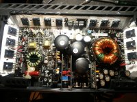
Attachments
Where is the third thermistor located? I will look again in a few minutes when I can get back to the amp.
I only found and checked the ones by the PS FETs and by the outputs on the other side of the board. When in thermal protection those two measurements 3.7v across each one. When not in protection one measured 4.1v and the other measured 3.9v across beach one. The amp was able to power up once again as long as I discharge the caps after turning it off and then turning it on again. It would go into thermal protection again shortly thereafter though..
I only found and checked the ones by the PS FETs and by the outputs on the other side of the board. When in thermal protection those two measurements 3.7v across each one. When not in protection one measured 4.1v and the other measured 3.9v across beach one. The amp was able to power up once again as long as I discharge the caps after turning it off and then turning it on again. It would go into thermal protection again shortly thereafter though..
Why does TH1002 have 12.5v on one side of it?
With the black probe on ground I get these measurements across the following:
TH1002: 12.5v and 4.8v on either side
R1005: 1.15v and -0.00v on either side
TH1001: 4.84v and 1.09v on either side
R1000: 1.11v and -0.03v on either side
TH1000: 4.90v and 1.014v on either side
With the black probe on ground I get these measurements across the following:
TH1002: 12.5v and 4.8v on either side
R1005: 1.15v and -0.00v on either side
TH1001: 4.84v and 1.09v on either side
R1000: 1.11v and -0.03v on either side
TH1000: 4.90v and 1.014v on either side
Generally, in rockford amps, the thermistor is fed 5v from the PS driver IC and is grounded through a resistor. The non-5v side is what you need to follow.
The diagram had not been released when I last checked. If you can get it, also request all of the driver board diagrams as well.
The diagram had not been released when I last checked. If you can get it, also request all of the driver board diagrams as well.
So I traced the side of TH1002 that has 12.6v on it. It goes to one side of R1006 / TP2 and also to the P100 connector of the BD Power Supply board. On the board it is directly connected to the D100 and D101 diodes.
In continuity test mode/diode check, It seems as if it connected to the pin next to it in P100 through a 47 ohm resistor and is also connected to another pin on the other connector, P101. The P100 pin has 13.4v while the P101 pin has 0.00v on it, but they both show a 48 ohm connection to the wire I am concerned about. The odd thing is that when those other pins are checked in diode check mode, they show a 0 ohms direct connection, even though they show different voltages...
In continuity test mode/diode check, It seems as if it connected to the pin next to it in P100 through a 47 ohm resistor and is also connected to another pin on the other connector, P101. The P100 pin has 13.4v while the P101 pin has 0.00v on it, but they both show a 48 ohm connection to the wire I am concerned about. The odd thing is that when those other pins are checked in diode check mode, they show a 0 ohms direct connection, even though they show different voltages...
Last edited:
Ok, so I think my problem has to do with the power supply driver board, or possibly the connection where the pins meet the board. There may be an intermittent connection or short at P100 or P101.
I had started to desolder the pins of P100 but after using my desoldering iron, I decided to resolder them and do further testing just in case I didn't have to pull the driver board. I powered up the amp after resoldering the pins and it turned on without thermal protection. I decided to take a reading of TH1002 while out of protection and got 0.9v on the same side that previously had 12.6v.
I reassembled the amplifier and was testing it with music and it was playing normally, but then it went into thermal protection again. I then have the power supply driver board a slight push towards the RCAs/rail capacitors and it came out of protection. As it is right now, if I leave the driver board vertically upright, it goes into protection, but if I push it towards the rail caps it comes out of protection. I will attend to the pin connectors in an attempt to get a good connection and report back.
The reason that I suspected a short (strand of wire) was because I don't see where 12 could originate, even if it has a bad via.
As a side note, the clearance around the header pins is generally so tight that the only way to remove the vertical boards with absolutely zero via damage is to have the solder for ALL pins molten at once. ChipQuik is the best option that I've found.
As a side note, the clearance around the header pins is generally so tight that the only way to remove the vertical boards with absolutely zero via damage is to have the solder for ALL pins molten at once. ChipQuik is the best option that I've found.
- Status
- This old topic is closed. If you want to reopen this topic, contact a moderator using the "Report Post" button.
- Home
- General Interest
- Car Audio
- Rockford P1000-1BD in thermal protection