Hey perry,
I have been repairing a T30001bd and notice that the driver sties are a bit different. They use a driver ic I am not familiar with. I replaced all the fets and rebuilt the driver circuits. I powered up the amp and started looking for the drive signal and only found it on 2 of 4 banks. I started checking the outputs of the uw3706ic and had square wave on one ic and not on the othe. I felt the one with no wave form and it was warm so replaced it from a donate amp. I ordered some new ones yesterday but curiosity was killing me. I powered amp and had square wave but then no square wave on the chip. These are a little different from the t40001bd series.
1. Should the be a drive signal on all 4 banks at the same time?
2. Do you have a schematic?
3. Does the drive signal look different on these compare to the t40001bd
If the output has no significant DC offset, all outputs should have drive signals.
email me if you want the 30001 diagrams I have.
babin_perry@yahoo.com
I don't know. I don't know if I ever had a 30001 to repair.
email me if you want the 30001 diagrams I have.
babin_perry@yahoo.com
I don't know. I don't know if I ever had a 30001 to repair.
Last edited:
I did notice during troubleshooting the driver circuit that using diode chk across pin 1 & 3 of Q400 and Q406 displayed 0.075v. I thought that was weird. I have 3 more to chk so I will compare to the other 3. Someone tried to repair this one before I got it and the tore tje mesha pads then installed the fets again with thermal grease with no clamping. I think they may did more damage than fixed. I replaced the mesh boards some I had and had to cut one in half.
The drive signal looks different compared to the t40001bd. It seemed like the duty cycle was 90% charging up then 10% off if that makes sense
The drive signal looks different compared to the t40001bd. It seemed like the duty cycle was 90% charging up then 10% off if that makes sense
At idle, you should see something close to 50%. Where there are drive circuit problems, the servo/feedback circuit may drive at something other than 50% to try to compensate for DC. Are you testing without rail voltage?
Testing with out rail voltage, using the trick you showed me. I clamped the scope grd on fet leg too. Not trying to get ahead of myself but do you have a source for the small coils/transformer connected to the driver ic?
I have 4 to repair and the green circuit board models have the tamura pht-102. If they are the same as the other models I found a source to purchase them.
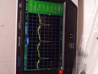
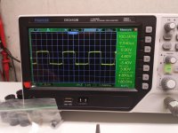
Perry I did scope probing this morning trying to find my drive signal with no luck. Interesting enough, the square wave on the output of the gate driver ic would change by cycling the power. I never had 4 drive signal 2 at most and they switch banks after power cycle...kinda weird. So I was looking for the pwm waveform. Is this suppose to be a square wave? Here is the waveform for both ic chips pin 2.
Attachments
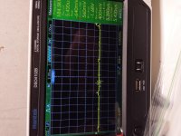
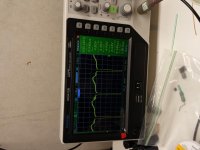
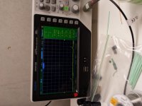
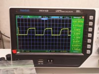
So not sure if that wave form is normal but I expect them to look the same at very least. Correct me if I am wrong. So now I checked pin 7 on U307 and U301 and this what I got. Oh pin 5 on both had a nice triangle wave form.
Attachments
Try soldering a resistor (1k-4.7k) between pins 1 and 2 of U301. Does the signal become closer to 50% duty cycle?
Perry I soldered a 1k across pin 1 and 2 and Bam!!! My drive signal was back and both gate drivers turned on at the same time... okay give me a second to see why that mic just happened. Then you can tell me why that worked.
S u nce I added that 1k resistor on the feedback loop it dropped the dc offset from 5v to nearly nothing. Since there was no offset then the amp thinks it is operating normally. Now does this mean I have an issue with u301 possibly causing the 5v offset?

I powered up the amp with the HV wires connected to see if I have audio. The FETS were operating correctly it seems and the rail voltage equilized. I did notice a 1.3 vdc on the output. I thought this was strange I connected the audio anyways just to check. With 60hz test signal I saw no audio.
The resistor closed the servo loop. Without it and without the output FETs operating, there was no feedback. The resistor gave it the feedback it was looking for.
Do you have audio at U300, pin 7?
Do you have audio at U300, pin 7?
I had audio signal up to switch 102 (subsonic). After cycling multiple times I have audio up to pin 7 of u300. Could this problem at switch 102 cause servo feedback issue?
I tried with the 1k removed no difference. Reinstalled 1k and tested amp and now I have clean audio. Thanks perry..on to the next 3!
No. The switch is well before that point but it could block the audio.
The 1k resistor can't be installed for normal operation. If the amp wouldn't function when the rails were connected, there is another problem.
If there os no feedback from the output, you could have a broken connection.
The 1k resistor can't be installed for normal operation. If the amp wouldn't function when the rails were connected, there is another problem.
If there os no feedback from the output, you could have a broken connection.
- Status
- Not open for further replies.
- Home
- General Interest
- Car Audio
- Rockford Fosgate T30001bd