This amp came in for repair and as usually there was another guy who attempted a repair before me.
After removing all output fets, cleaning the board and replacing both uc3706s, i powered the amp.
It powers up ok (power led on)
All auxiliary voltages are present.
There was a nice carrier triangle
The main issue is that one bank of the floating 120V output shows 4V and the other one around 185V (referenced to the GND pin).
I read the other threads regarding this issue, but R54, R55, R56, R65, R13 and R53 are all ok.
Additionally Q8, Q11 and Q12, all test ok.
I even tried to measure the power terminals with two different multimeters, and i got the same results.
Do the output fets have to be on in order to have proper readings?
This amp came in for repair and as usually there was another guy who attempted a repair before me.
Shame the other guy didn't know about this forum. He could have come here and had someone else fix it for him the first time around. Best of luck with it
")
I've never tried powering one up without the outputs in the circuit. The high-side drive is floating so it's difficult to say what you'll read on it. If you want to check the drive signals, you'll need to do so directly across the gate and source legs of the output transistors.
This will be most definitive if you use your scope in differential mode.
You can use a multimeter to see if all drive signals give the same DC voltage readings but it won't be definitive.
You can use a scope in normal mode but you'd have to ground the various FET source legs. I've never tried it in this amp but it shouldn't be a problem. If you try this, I'd suggest inserting a 1 amp fuse or a 1 ohm 1/4w resistor between the FET source leg and ground so that it can open the circuit if there is a problem. Each group of FETs would have to have one FET source grounded when checking the drive signal. You should only have one group grounded at any time.
You would not need to ground the sources for the FETs in the bank with Q430 since they're already grounded.
Again, this is assuming that there are no output transistors in the circuit and no solder bridges between any of the solder pads for the output transistors.
Shame the other guy didn't know about this forum. He could have come here and had someone else fix it for him the first time around. Best of luck with it
LOL!!! I sense something here, not sure what yet, but damn this is fun to watch!!
Back to work after two days in bed with the flu...
I dont really see any advantage in trying to figure out if everything is ok with this amp without the output fets on.
I am not interested in taking a different path regarding the repair of such amps neither....
So, before i put back a fresh set of output fets, i did some testing.
Both uc3706 have a nice square wave in pins 1 and 16 (toggle A and B), if that is of any significance and 10V on pin 8 and pin 3 has around 6V (the chip is enabled).
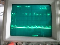
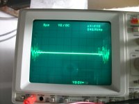
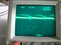
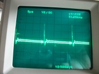
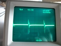
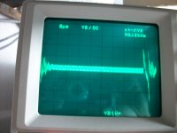
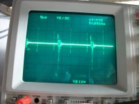
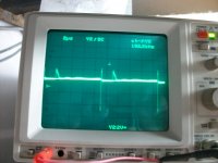
Now, after groundind each bank of fets (source pin of each bank with 1 ohm resistor to gnd) i got the following pics. I believe only two banks have a pulse
Please note i turn on the amp with the 12V supply current limited to 4A and it takes some time to charge the filter caps.
I dont really see any advantage in trying to figure out if everything is ok with this amp without the output fets on.
I am not interested in taking a different path regarding the repair of such amps neither....
So, before i put back a fresh set of output fets, i did some testing.
Both uc3706 have a nice square wave in pins 1 and 16 (toggle A and B), if that is of any significance and 10V on pin 8 and pin 3 has around 6V (the chip is enabled).
Now, after groundind each bank of fets (source pin of each bank with 1 ohm resistor to gnd) i got the following pics. I believe only two banks have a pulse
Please note i turn on the amp with the 12V supply current limited to 4A and it takes some time to charge the filter caps.
Attachments
6 and 11 are the output pins. Do you have a square wave on those pins?
Checking the drive signals with no outputs helps find problems that would destroy the outputs if the amp was powered up while with them in the circuit.
I don't know what you mean by 'different path'. If you're referring to using the amp in differential mode, it's important because it allows you to view signals that would otherwise be difficult to see in high resolution (particularly in regards to DC levels).
in the area around the fets (where the copper traces are wider) all (drains and sources) appear to be ok.
Will try again though.
But, now i get the following readings on U301 and U302
U301
1. 4.70
2. 0
3. 1.54
4. -5.88
5. 0.102
6. 4.75
7. -4.10
8. 6.20
U302
1. 4.25
2. 0.245
3. 0.125
4. -5.88
5. 0.071
6. -4.23
7. 5.80
8. 6.20
I also grounded the source of each bank of fets (one at a time), and probed the gate
Attachments
IC300
Pin 1: 3.66
Pin 2: 0.085
Pin 3: 0.100
Pin 4: -5.85
Pin 5: 4.00
Pin 6: 4.00
Pin 7: 4.10
Pin 8: 6.30
IC306
Pin 1: -4.25
Pin 2: -1.50
Pin 3: -1.60 (i know this is correct)
Pin 4: -5.88
Pin 5: 0.078
Pin 6: 0.090
Pin 7: 4.480
Pin 8: 6.30
IC307
Pin 1: 0.12
Pin 2: 0.099
Pin 3: 0.085
Pin 4: -5.88
Pin 5: 0.090
Pin 6: 0.086
Pin 7: 0.170
Pin 8: 6.30
- Status
- This old topic is closed. If you want to reopen this topic, contact a moderator using the "Report Post" button.
- Home
- General Interest
- Car Audio
- Rockford Fosgate T30001bd