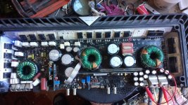
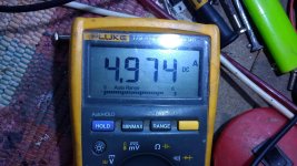
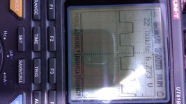
Good morning everyone, today trying to repair this t2500.1bd, it had already been tried to repair, or obviously they did not succeed, the first problem I see is a consumption of 5 amps without load and with the diodes (4) removed from the card main, the mosfets of the source that go in the first transformer are those that heat up (6 mosfets) the only difference that I see with the source of the center is a slight increase in the gate voltage, let's see what you think
Attachments

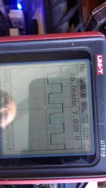
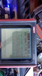
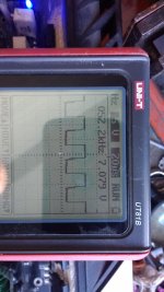
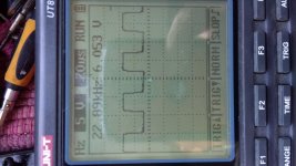
In the second capture of the square wave a frequency lower than the rest is seen, this I suppose is causing the problem, since the second source is working well I can discard the oscillation control card
Confirm that the source legs for all of the PS FETs are at ground (not floating or pulsing. At precisely the same voltage as the ground terminal.
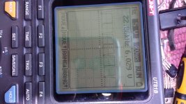
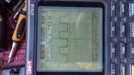
The frequency cannot be different. The scope was having trouble reading, due to noise, most likely.
After the above, remove B+ from the amp (have only ground and remote) and re-check the 4 gate waveforms.
The frequency cannot be different. The scope was having trouble reading, due to noise, most likely.
After the above, remove B+ from the amp (have only ground and remote) and re-check the 4 gate waveforms.
This is confusing because you're not using any circuit board designations.
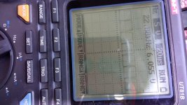
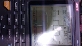
I don't see any problem with the waveforms. I'm assuming that you (whoever) used exact replacement values for any burned resistors and FETs.
One transformer (T1000) has additional windings that produce driver voltages. I don't know if that's the transformer for the heating FETs.
I don't see any problem with the waveforms. I'm assuming that you (whoever) used exact replacement values for any burned resistors and FETs.
One transformer (T1000) has additional windings that produce driver voltages. I don't know if that's the transformer for the heating FETs.
In reality, the mosfets and resistors of the transformers are the original ones of the device, they are the ones that it brings from the factory, since the amplifier has never been modified or repaired, the repair that it has so far is in the output stage.
the transformer that where the mosfets are heated is the T1
the transformer that where the mosfets are heated is the T1
I think this may be normal.
In this amp do all of the FETs for T1 have 60.4 ohm resistors?
While the other transformer has 60.4 for 3 FETs and 47.5 for the other 3 FETs?
In this amp do all of the FETs for T1 have 60.4 ohm resistors?
While the other transformer has 60.4 for 3 FETs and 47.5 for the other 3 FETs?
Yes, it is correct with the values of the resistors that you comment.
The funny thing is that t1 mosfets heat and consume 5 amps, while t1000 mosfets stay cold
The funny thing is that t1 mosfets heat and consume 5 amps, while t1000 mosfets stay cold
That could be due to the lower value of the gate resistors of half of the FETs that don't heat up.
If possible perry, however, reviewing a theory arises, the gates of the t1000 mosfets go directly to the oscillation control card, unlike the gates of the t1 mosfets, those go to a circuit on the card main, i guess its not to overload the oscillation control card, i want to think that the heating problem in t1 is there.
Attachments
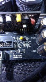
You could replace 3 gate resistors with a lower value (that of the other transformer) and determine whether that's the problem or not.
replace the gate resistors of the 47 ohm t1000 mosfets with the 60 ohm ones and the fault persists.
To clarify, are you saying that you replaced 3 of the 60.4 ohm gate resistors for the FETs that were heating up with 47 ohm resistors and those FETs continue to heat up to the same degree as they previously heated?
- Home
- General Interest
- Car Audio
- Rockford Fosgate t2500.1bd problem