Hi everyone. Sorry for my English.
I have a T2500BD amplifier in repair. It was used in half ohm and burned the output mosfet and smd drivers. All were replaced, the module works, turns on correctly, there is audio "no load". The problem is when I connect a load, a subwoofer or my load resistance, it comes into protection when I raise the audio level.
It has about 3.2 amps at rest, begins to consume when I raise the level and turn on the yellow LED. Anyone had experience with this fault?
Thank you very much to all.
Attachments
Have you tried to get a schematic diagram from Rockford?
Have you tried a really light load to see if you could see some sort of problem in the output before it goes into protect?
Do you have a strong drive signal to all 4 banks of output section FETs?
Have you tried a really light load to see if you could see some sort of problem in the output before it goes into protect?
Do you have a strong drive signal to all 4 banks of output section FETs?
Thank you very much Perry for your help.
Diagrams ask Rockford but they don't send. I am in Argentina and we do not have an official technical service of the brand.
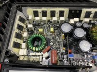
Attached photo of the exit gate.
Immediately I raise the gain is put on protection.
I don't know if overload or short circuit protection can be overridden. The strange thing is that music comes out and works, when I lift short.
I raise the level and it is put in protection with about 5 amps of consumption.
Diagrams ask Rockford but they don't send. I am in Argentina and we do not have an official technical service of the brand.
Attached photo of the exit gate.
Immediately I raise the gain is put on protection.
I don't know if overload or short circuit protection can be overridden. The strange thing is that music comes out and works, when I lift short.
I raise the level and it is put in protection with about 5 amps of consumption.
Don't adjust the level with the gains on the amp. Do this at the source unit so you're not changing two different things on the amp (gain position AND output level). You want only one variable.
With a lighter load, can you get a higher amplitude at the output of the amp?
Does it always trip at 5 amps?
Is the voltage dropping at the 12v input terminals of the amp?
With a lighter load, can you get a higher amplitude at the output of the amp?
Does it always trip at 5 amps?
Is the voltage dropping at the 12v input terminals of the amp?
I tell you, if I charge with 4 ohms, it also comes into protection.
Without placing a load on the output, with the maximum input level it comes into protection.
What I notice is that they heat the 6 mosfet of the source on the right side, when the other 6 are still cold. In all gate I have the square.
At the entrance there are always 12 volts in all tests. They do not go down at any time.
I await any indication. Thank you
Give circuit board designations when listing components.The language barrier makes things difficult. We need to eliminate all possible problems and designations help.
What are you calling an 'entrance'?
Is the square wave clean on the falling side and does it go all of the way back down the the voltage on the source leg?
I suggest testing without rail voltage to check the drive signals. As a second option, using a mains powered scope in differential mode or using a battery powered scope to check signals with rail voltage.
Good morning Sebastian, I'm from Panama and I'm working on an amplifier like yours, I wrote to Rockford and they gave me the diagram, but only for the version of bd no cp and the truth will help you a lot, Perry already sent it to you so that You have it and can continue to help write to my email Sebastian for albis.calderon @ gmail.com in Spanish, of course, it is our language and I will send the service diagram close enough and once the transformers arrive we can exchange information and help each other.
Regards,
Regards,
Thanks Albis for the schemes.
I call entrance to the source, it is working delivering 100 volts on the rail. The mosfet have a clean and stable square. It deforms when it comes into protection, as does the signal from the exit gate.
They told me to take out the protection led, to verify what is happening. I notice that they heat the mosfet of the source q1,2,3,4,5 and 6. The other 6 are cold.
When he wants to enter into protection, what he does is start to sound the toroids of the source. The squares of the gate are deformed at the source, and consequently they are also deformed at the exit stage. The behavior really confused me. Reitetro, in low volume everything works perfectly. Thank you
Since both power supplies are essentially in parallel, if both are producing output, it would appear that the FETs that are getting hot have a problem with the drive circuit.
- Home
- General Interest
- Car Audio
- Rockford Fosgate T2500-1bd in YELLOW PROTECTION