U301
Pin 1:-4.47
Pin 2:0.41
Pin 3:0.00
Pin 4:-5.98
Pin 5:0.00
Pin 6:-4.43
Pin 7:5.88
Pin 8:6.08
U302
Pin 1:4.44
Pin 2:0.00
Pin 3:0.00
Pin 4:-5.98
Pin 5:0.00
Pin 6:4.44
Pin 7:-4.30
Pin 8:6.08
Pin 1:-4.47
Pin 2:0.41
Pin 3:0.00
Pin 4:-5.98
Pin 5:0.00
Pin 6:-4.43
Pin 7:5.88
Pin 8:6.08
U302
Pin 1:4.44
Pin 2:0.00
Pin 3:0.00
Pin 4:-5.98
Pin 5:0.00
Pin 6:4.44
Pin 7:-4.30
Pin 8:6.08
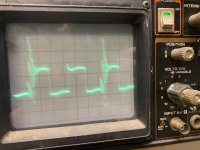
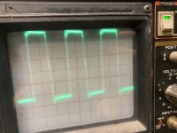
Ok sorry for the confusion. The jumper came unsoldered from R315 I soldered off back in place and get a square wave on pin 7 of both ic’s . On R309,322 I get a square wave on both sides of those resistors
In BD amps, half of the 'output' FETs are rail switchers. The other half are the audio FETs.
Check Q405.
Check Q405.
That's the entire path. I don't really see any problem.
Can you use your scope in differential mode?
Can you use your scope in differential mode?
Measure the rail voltage across the drain of Q419 and the source of Q428.
Measure the rail voltage between those points and ground, before and after removing the jumper.
Remove the jumper and recheck for audio.
Measure the rail voltage between those points and ground, before and after removing the jumper.
Remove the jumper and recheck for audio.
With black probe on drain of Q419 and red probe on source of Q428 without jumper I get -103.7
Black probe on ground red probe on source of Q419 I get 103.8
Black probe on ground red probe on source of Q428 I Get 0.00 volts
All of these readings are with jumper removed
With jumper in place I get
Drain to source -101.7
With black probe on ground and jumper in place I get 103.1 on source of Q419
I get 52.1 volts on drain of Q428 with black probe on ground
hopefully I did this right if not what measurements do you need ?
I also noticed I get 1 volt of DC on pin 1 of all opamps that sit behind rca jacks and I removed jumper and get distorted audio still
Also the mesh’s board for Q419,418,428,427 has something soldered to TC5 which I’m assuming is for bias .
Q412,411,405,404 both of those Kesha boards don’t have anything soldered to them is this normal for this amp or is it missing ?
Last edited:
Let's try this in a different way.
Jumper in place for all.
Black on ground.
Q419 drain (center leg)?
Q419 source leg?
Q428 source?
Q405 drain (center leg)?
Q405 source leg?
Q412 source?
Jumper in place for all.
Black on ground.
Q419 drain (center leg)?
Q419 source leg?
Q428 source?
Q405 drain (center leg)?
Q405 source leg?
Q412 source?
Jumper in place and black probe on ground
Q419
Drain:101.3
Source:51.2
Q428
Source:0.00
Q405
Drain:101.5
Source:0.00
Q412
Source:0.00
Q419
Drain:101.3
Source:51.2
Q428
Source:0.00
Q405
Drain:101.5
Source:0.00
Q412
Source:0.00
- Home
- General Interest
- Car Audio
- Rockford Fosgate T20001bd