How can pins 1 and 2 be different if you soldered a bridge between them?
Why are the readings different for pin 1 between posts 22 and 24?
Why are the readings different for pin 1 between posts 22 and 24?
Not sure maybe I don’t have a good enough solder bridge between pins 1 and 2 .
And when I first touch pin 1 I get 4 volts and it finally rests at -1.89
And when I first touch pin 1 I get 4 volts and it finally rests at -1.89
Ok redid the solder bridge between pins 1-2
Pin 1:0.00
Pin 2:0.00
Pin 3:0.00
Pin 4:-6.01
Pin 5:0.00
Pin 6:0.00
Pin 7:0.16
Pin 8:6.08
Pin 1:0.00
Pin 2:0.00
Pin 3:0.00
Pin 4:-6.01
Pin 5:0.00
Pin 6:0.00
Pin 7:0.16
Pin 8:6.08
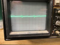
U301
Pin 7:0.18
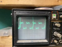
U302
Pin 7:0.19
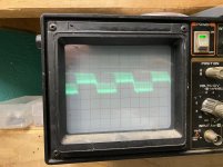
First image is U301
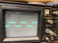
2nd image is U302
If you look closely you can see the square wave in the first pic but that’s the best I can get my scope to show the waveforms
Pin 7:0.18
U302
Pin 7:0.19
First image is U301
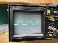
2nd image is U302
If you look closely you can see the square wave in the first pic but that’s the best I can get my scope to show the waveforms
Attachments
Did you try adjusting the trigger level?
Does going from 5v/div to 2v/div help to make it trigger?
Does going from 5v/div to 2v/div help to make it trigger?
Which pins of the U3706 driver ICs have square waves (or other pulsed waveforms)?
What is the DC voltage on pin 3?
What is the DC voltage on pin 3?
U400 pin 3:5.44
U401 Pin 3:5.44
U400
Pins 1,2,11 have square wave forms
Pins 6,16 have square wave forms but very distorted and the ic gets warm to the touch
U401
Same as U400
U401 Pin 3:5.44
U400
Pins 1,2,11 have square wave forms
Pins 6,16 have square wave forms but very distorted and the ic gets warm to the touch
U401
Same as U400
- Home
- General Interest
- Car Audio
- Rockford Fosgate T20001BD