Anyone have a schematic for this amp ?
Or can tell me the value of the gate resistors for the power supply I know they use 2 different values
Or can tell me the value of the gate resistors for the power supply I know they use 2 different values
I don't have PS photos from a CP but on similar amps, the 3 FETs on the back of the heatsink use 47.5 ohm. The 3 on the side use 60.4 ohm.
Do you have a picture of the output area around the inductor ?
Wondering if anything goes in the following locations R2035,C2009,C2006
Wondering if anything goes in the following locations R2035,C2009,C2006
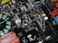
I’m almost done repairing this amp .
The power supply driverboard was missing in this amp .
Do you happen to know if the driver boards are the same in the 1500-1bd and the T1500-1bdcp ?
The power supply driverboard was missing in this amp .
Do you happen to know if the driver boards are the same in the 1500-1bd and the T1500-1bdcp ?
Found a power supply driver board for it .
Do you happen to have a pic of the driverboard there are some missing parts on the one I have .
Do you happen to have a pic of the driverboard there are some missing parts on the one I have .
http://www.bcae1.com/temp/DSCN9667x.jpg
http://www.bcae1.com/temp/DSCN9671x.jpg
They are full resolution so make sure that you're viewing them at 100% (only about 1/4 will fit on your monitor).
http://www.bcae1.com/temp/DSCN9671x.jpg
They are full resolution so make sure that you're viewing them at 100% (only about 1/4 will fit on your monitor).
Thanks for the pics .
Got the amp powered up .
Now the problem is 1 output Q214 gets hot within 5 secs. I checked the gate resistor and replaced Q2017,Q2019 but same issue the output heats up and amp draws 5 amps of current at idle
Got the amp powered up .
Now the problem is 1 output Q214 gets hot within 5 secs. I checked the gate resistor and replaced Q2017,Q2019 but same issue the output heats up and amp draws 5 amps of current at idle
I've found that those 2 FETs heat more than the others in the CP amp but both should heat approximately evenly. Confirm that you read 0 ohms between the corresponding terminals of those two FETs.
Read 0 ohm between the corresponding terminals of the 2 output fets .
Q2014 heats up within 5 secs to the point where you cannot touch it without getting burned .
The other fet remains much cooler
Q2014 heats up within 5 secs to the point where you cannot touch it without getting burned .
The other fet remains much cooler
If you have a good signal, I think they're mismatched. The threshold isn't always close enough, even with matching date codes.
Unless you have an isolated scope (battery powered) or can use your scope in differential mode, I'd suggest desoldering the center legs of the rectifiers and checking the drive signal. With the rectifiers out, you can ground your mains powered scope to the source leg of the FETs to get a good view of the signal.
Unless you have an isolated scope (battery powered) or can use your scope in differential mode, I'd suggest desoldering the center legs of the rectifiers and checking the drive signal. With the rectifiers out, you can ground your mains powered scope to the source leg of the FETs to get a good view of the signal.
Desoldering the rectifiers may tell you if you have a bad signal.
Did you buy the FETs from a reputable, authorized distributor (not ebay)?
Did you buy the FETs from a reputable, authorized distributor (not ebay)?
Amp has distorted output .
Here are the voltages I get wanna know if these look correct or I have a problem somewhere .
Q2010-MJD44H11: -10.88
Q2012-MJD44H11: -10.76
Q2001- MJD44H11: -15.54
Q2000-MJD45H11: 20.33
The black probe was placed on the tabs of the parts when measuring voltages
Here are the voltages I get wanna know if these look correct or I have a problem somewhere .
Q2010-MJD44H11: -10.88
Q2012-MJD44H11: -10.76
Q2001- MJD44H11: -15.54
Q2000-MJD45H11: 20.33
The black probe was placed on the tabs of the parts when measuring voltages
- Home
- General Interest
- Car Audio
- Rockford Fosgate T1500-1BDCP