The originals are 10 ohms. If none or just a few need to be changed, I leave the 10 ohm. Some people use 47 ohms. I think that's a bit high for the IRFP064 (originals were the HUF75339G).
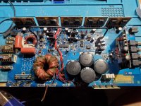
The diagram says 330uF@16 but you have plenty of overhead space so I'd use something like the 63v. The higher voltage will have lower ESR.
The diagram says 330uF@16 but you have plenty of overhead space so I'd use something like the 63v. The higher voltage will have lower ESR.
I installed a few huf75344G and all 20R gate resistors. Drive was present. When i applied b+ I got high current a bad short somewhere. It pulled the voltage down from 13.08vdc to 6.7vdc badly. So I unhooked the twisted pair same result.
I did they looked ok then. Rechecking them they were off.
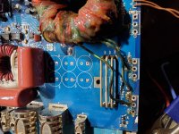
This is how the drivers are placed.
Q17 mspa56
Q20 mspa06
Q19 mspa56
Q21 mspa06
Is this correct?
This is how the drivers are placed.
Q17 mspa56
Q20 mspa06
Q19 mspa56
Q21 mspa06
Is this correct?
I'm having a problem with the npn and pnp placement. If I use how it was in the amplifiers the signal shuts down. Do you have a shcematic for this amplifier?
Sorry Perry didn't even see it. Anyway thanks. So now my issue is I need to decide on what to use as a new insulator as someone has taken 2 of the 3 mesha insulators for the power supply mosfets. Blue silicone pad, silicone tape, kapton?
It's probably not critical but you need to use the same insulator on all FETs that are in the same bank. My first choices would be mica or Kapton MT (not the clear stuff). That said, any of the ones you listed will be OK. Bear in mind that clamping pressure is especially important for the silicone insulators.
- Home
- General Interest
- Car Audio
- Rockford Fosgate RF-X6, power supply help