No luck ... I replaced LM339 but the result is the same ...
I will continue investigating, and when I receive TL494 I will try my luck again ..
I will continue investigating, and when I receive TL494 I will try my luck again ..
If this is an Asian design, look for a PNP transistor connected between pins 13/14 and pin 4 of the 494. If it's there and you lift/remove it, it may allow the amp to power up but be careful because it would also defeat the protection circuit.
Yes, I'm sure this is an Asian model
I found that driver, it was a 2GM, I removed it and connected the amplifier, but everything is the same, nothing has changed ...
I found that driver, it was a 2GM, I removed it and connected the amplifier, but everything is the same, nothing has changed ...
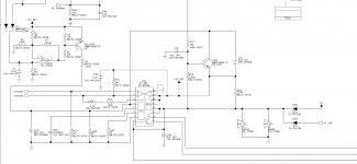
Thank you very much Motronix for this scheme, I'm sure it will give me some light in this matter.
Perry,
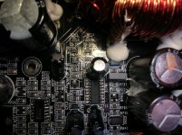
Right terminal of R754 and positive terminal of C710 show 5V measured with the polymeter, (black test tip to negative of the amplifier)
Anyway, these two components show 5V in their two terminals ... weird?
Perry,
Right terminal of R754 and positive terminal of C710 show 5V measured with the polymeter, (black test tip to negative of the amplifier)
Anyway, these two components show 5V in their two terminals ... weird?
Which components have terminals that read 0 ohms to pin 14 and 0 ohms to pin 4?
What is the resistance from pin 4 to pin 14?
What is the resistance from pin 4 to pin 14?
josesony68 it looks like your amplifier in Protection mode or the 12v remote power not reach the TL494 and the LM339.
from your pictures i see that the LM339 legs solder is not so good and maybe some of them shorted. the TL494 & LM339 must get 12V (TL494 at pin 8,11,12 and LM339 pin 3) if you can read this 12V then you need to see what make your amplifier get into Protection mode. if you have on TL494 pin 4: 4,98V this mean it is in protection mode
from your pictures i see that the LM339 legs solder is not so good and maybe some of them shorted. the TL494 & LM339 must get 12V (TL494 at pin 8,11,12 and LM339 pin 3) if you can read this 12V then you need to see what make your amplifier get into Protection mode. if you have on TL494 pin 4: 4,98V this mean it is in protection mode
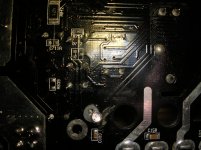
0 ohm to pin 14 of TL494:
positive of C710, right terminal of R754 and emitter of Q703.
0 ohms to pin 4 of TL494:
negative of C710, left terminal of R754, right terminal of R711 and collector of Q703.
Resistance of pin 4 to pin 14 of TL494:
It starts at 400K and decreases after one minute stabilizes at 320K
positive of C710, right terminal of R754 and emitter of Q703.
0 ohms to pin 4 of TL494:
negative of C710, left terminal of R754, right terminal of R711 and collector of Q703.
Resistance of pin 4 to pin 14 of TL494:
It starts at 400K and decreases after one minute stabilizes at 320K
motronix:
in pin 3 of LM339 I have 4.98V
pins 8,11,12 of TL494 I have 12,26V
Thanks for your suggestions.
in pin 3 of LM339 I have 4.98V
pins 8,11,12 of TL494 I have 12,26V
Thanks for your suggestions.
C703 is near the positive remote and one of its terminals is connected to the negative of the amplifier, correct?
I'm going to try it, but I'll do it tomorrow, today it's too late for me ...
I'm going to try it, but I'll do it tomorrow, today it's too late for me ...
I have extracted C710, I have measured it, but its reading is correct.
I will wait until I receive a TL494 and I will try to replace it ...
I will wait until I receive a TL494 and I will try to replace it ...
- Home
- General Interest
- Car Audio
- Rockford fosgate R 750 1D