First of all, I apologize for the numerous inquiries regarding various amplifiers recently. I tend to set aside those that I cannot comprehend until I acquire more knowledge about the repair process, and I attempt to repair them occasionally.
@Perry Babin
I apologize for having to bring this up, but I find myself frustrated with this issue and feel the need to start afresh, if you understand my sentiment. You are indeed correct, and I believe I mistakenly confused pin 18 with pin 13. I am receiving PWM signals on pins 13 and 16. I had to replace several output transistors, which allowed the amplifier to display a blue light, yet there is still no output. I am hearing a popping noise, and when I observe the Oscilloscope, I can see it attempting to build signal but producing pops instead. What do you suggest I should examine? I have uploaded a video where you can hear the popping sound. Video Here
Thanks
Did you try to get the diagrams from Rockford?
Image of the drive at the output FETs when the rectifiers were out of the circuit?
Image of the drive at the output FETs when the rectifiers were out of the circuit?
I wanted you to check the gate-source drive for each bank of outputs (there are 4 banks) with the rectifiers out of the circuit.
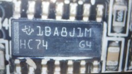
I resolved the issue; it was both 1BA8J1M on the driver board. I am unsure how both components failed simultaneously; is this a common occurrence? I am grateful for all your assistance.
- Home
- General Interest
- Car Audio
- Rockford Fosgate Punch P1000X1BD