Output transistors?
Abuse, random failure, shorted speaker wire?
It's a bit odd that both shorted to precisely the same resistance. Or is 0.5 the same as what your meter reads when you hold the probes together?
Abuse, random failure, shorted speaker wire?
It's a bit odd that both shorted to precisely the same resistance. Or is 0.5 the same as what your meter reads when you hold the probes together?

I'm not sure but they did it on other amplifiers (using 60.4 and 47.5 ohm).
The 1310s aren't likely original.
Contact Rockford to see if they will send you the diagram, or at least tell you what the PS parts should be.
The 1310s aren't likely original.
Contact Rockford to see if they will send you the diagram, or at least tell you what the PS parts should be.
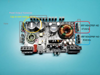
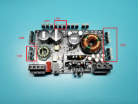
Apologies, the 1310 refers to the output FETs. The power supply utilizes the IRF1404ZPBF-ND.
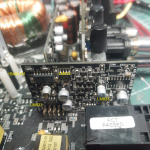
I have not encountered this before, which is why I inquired. The image illustrates the correction and highlights the capacitor that is overheating; at 10 volts and 3 amps, it triggers the Over Current Protection (OCP). I have tested all the new FETs as well as the others, and all have passed the tests.
Q: What could be the reason for the capacitor overheating and activating the OCP?
Attachments
The cap could be defective.
Are those PS FETs the original part number. The gate resistor values you listed are high for those FETs.
Why do you think it's OCP? It's likely low-voltage protection.
Are those PS FETs the original part number. The gate resistor values you listed are high for those FETs.
Why do you think it's OCP? It's likely low-voltage protection.
Q: Are those PS FETs the original part number.
A: I am convinced that the amplifier was in its original state before I acquired it, and that six power FETs along with two output FETs have malfunctioned. I have replaced all of them and observed the offset resistors on the power supply side. I repaired the output transistor as you suggested (thank you for that), but now the capacitor is overheating. It attempts to power on but activates the Over Current Protection (OCP) at 12.8 volts and 6 amps. I do toggle the OCP to ensure the capacitors are charged. This issue only arises when the remote wire is energized. When only the power and ground wires are connected, everything functions properly, with an amperage of .005 and no voltage.
The Overcurrent Protection (OCP) feature on my power supply is equipped with an OCP button. When I set the current limit to 10 amps, the power supply will automatically shut down if the amplifier exceeds this threshold, and it will begin to blink until I initiate a reset. For an amplifier of this size, I will start with 5 amps and 10 volts, and if the OCP activates, I will gradually increase the voltage to 12.8 volts. If it continues to shut off, I will then raise the current limit to 10 amps. Should the OCP engage, it indicates that the amplifier may be damaged. The OCP has proven to be invaluable, as I previously experienced equipment failures when I did not utilize it. I now rely on it consistently. I will assess the amplifier's wattage to appropriately adjust the voltage and current settings. As an expert in amplifiers, would you consider this approach to be sound, or do you recommend an alternative method?
I thought you meant the amp's OCP.
Are the PS FETs heating up?
Do you have a dummy load resistor of about 2 ohms that you could insert in the B+ line?
I absolutely hate the OCP of a 12v supply. The inline current limiter is better in virtually every possible way.
I'm no expert.
Are the PS FETs heating up?
Do you have a dummy load resistor of about 2 ohms that you could insert in the B+ line?
I absolutely hate the OCP of a 12v supply. The inline current limiter is better in virtually every possible way.
I'm no expert.
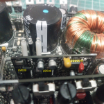
I employed two 4-ohm 500-watt capacitors to establish a 2-ohm configuration. Upon initiation, some FETs on the output side attained a temperature of 114°F. The popping noise recorded in the video is produced by both speakers, and the accompanying image demonstrates the operation of the FETs. Here is the video. I am considering whether I may have overlooked a faulty transistor. Oh and the Cap is no longer heating up. is that the work of the Caps
Attachments
I don't think the PS FETs should be heating up.
both speakers? Isn't thins a mono amplifier?
As of now, what's the DCV across the rail caps?
Pull the rectifiers. Do the PS FETs still heat up?
both speakers? Isn't thins a mono amplifier?
As of now, what's the DCV across the rail caps?
Pull the rectifiers. Do the PS FETs still heat up?
Q: Are both speakers connected? Is this not a mono amplifier?
A: Yes, it is mono; however, it features A and B speaker outputs. I am unsure why I mentioned both, as I realized I had both of my test speakers connected.
Q: Currently, what is the DC voltage across the rail capacitors?
A: The rail voltage measures 48 volts.
The power supply FETs do not experience significant heating, but the three located to the left of the rectifiers reach temperatures of 215 degrees Fahrenheit. I did not observe any heating in them when the rectifiers were installed.
Are the rectifiers out?
I need a photo of the BD driver board.
Did you try to get the diagrams from Rockford?
I need a photo of the BD driver board.
Did you try to get the diagrams from Rockford?
Confirm that you don't have any DCV on any of the FET source legs. If it's all essentially 0v, check the drive signals of all output FETs. Scope ground on the source leg ans probe tip on the gate leg. DC coupling. Do all drive signals have an amplitude of about 10v and do all go back to very near ground?
Q: Confirm that you don't have any DCV on any of the FET source legs
A: Indeed, the voltage will increase to between 8 volts and 9 volts; however, when the speaker emits a pop, it quickly falls back to 0 volts, making it challenging to obtain an accurate voltage measurement.
In summary, the power supply functions properly when the rectifiers are removed. However, when the rectifiers are installed, there is no signal detected on any of the output FETs. During the testing of the UC3526A, signals can be seen on pins 16 and 18, varying in line with the audio output from the speakers. It seems that the signal accumulates to a specific threshold before it drops. Furthermore, it's important to note that under typical conditions, the amplifier takes about 8 to 10 seconds to power up and stabilize before it falls, while probing the gate pin for a signal causes the rise and fall to happen every 3 seconds.
The confirmation of 0v and the signal check on the outputs is with the rectifiers removed. The speakers won't pop without the rectifiers.
No pop with rectifiers removed.
Without the rectifiers, I achieve excellent PWM on the pads where the rectifiers were located.
Without the rectifiers, I achieve excellent PWM on the pads where the rectifiers were located.
I replaced a 0-ohm resistor that was covered in rubber, which initially measured 20k. After the replacement, it measured 0.10, yet the amplifier does not exhibit any rise and fall or popping sounds when the rectifiers are connected. I observe that the power FETs attempt to generate PWM but fail every two seconds. The gate pins of the output FETs show no voltage, registering 0 volts across all four groups. On the UC3526A, square waves are visible on pins 16 and 18, while a sawtooth wave appears on pin 10.
The ADW is the 18 pin package but the pins that you listed with the signals don't match up. They don't even match up for the 20 pin package.
I need you to do whatever is (will be) necessary to check the output drive. That needs to be done without the rectifiers.
I need you to do whatever is (will be) necessary to check the output drive. That needs to be done without the rectifiers.
- Home
- General Interest
- Car Audio
- Rockford Fosgate Punch P1000X1BD