Hello everyone.
I have a Punch 400.4 board number PC-0954C looks to be the same board as the 400X4 transana.
I recieved the amp in with 2 channels working. The 2 channels that did not one had 26.50 vdc on it and the other had distortion, and sometimes it had a constant thumping.
I fixed the channel with the thumping, it was a combo of a broken rca shield ground pin and a faulty x-over card slot. This channel now produces audio but will not bias. If you max the bias pot fully clockwise it will draw some current but is significantely higher in adjustment than the working channels. It may be due to the new outputs, not sure. The output for this channel does look clean on the scope.
The other channel will not bias either and still has distortion.
What has been done so far:
Q414, Q419, Q315, Q319 IRF540 and IRF9540 output fets have been changed.
R463, R436, R363, R336 source resistors have been changed.
Q410 and Q310 MPS6521 bias transistors have been changed.
Q413, Q421, Q412, Q422 MPSA06 and MPSA56 driver transistors have been changed.
R449 was missing from the board due to extreme heat from the looks of the solder which was a 150ohm resistor. I replaced it with a new one.
The 4 series channel still has distortion and will not bias. It does not have any DC on the bridging terminal for this channel. Looking for some advice as where to go next.
Also if anyone has a schematic for this board that would be great too!!
Last edited:
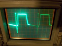
Im still having trouble. I just dont understand how the output can look clean on the scope but be distorted through the speaker. The only time the signal looks funny is well into hard clipping.
I have been testing various components vs working channels and still no luck yet.
I have been testing various components vs working channels and still no luck yet.
Are you saying that if you drive a 100HZ sine wave into the amp with a speaker or dummy load connected to the speaker terminals that the signal looks perfectly clean right up to clipping but it sounds distorted?
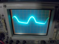
No... without a load or speaker hooked up driving a 100hz sine wave into the amp with the scope set at 10vol/div 2 ms the amp has a clean signal on the scope up until hard clipping then it looks distorted.
If you hook up a speaker to the amp and play a musical CD the sound is distorted and the higher you turn the volume the worse it gets.
I put my meter on the bridging terminal of that channel and as the volume is increased DC begins to appear and increases with the volume. There is no DC on the bridging terminal at an idle.
If I max out the bias pot fully clockwise on the 3 series channel it will just start to pull a small amount of current. Usually a channel still has an issue when it wont bias but not always. This channel has clean audio. All the other channels are matching as far as pot orientation except this one.
The protection circuit transistors monitor the voltage across the 0.1 ohm source resistors and have one that clamps the drive signal to the outputs. When the outputs fail (and especially when the 0.1 ohm resistors fail) the protection circuit transistors fail.
Lifting the diodes (high or low side, depending on whether the top or bottom is clipped) disables the protection circuit to allow you to determine if there is a problem with the protection circuit or the audio circuit.
Does any other channel have output transistors from the same batch as channel 3?
Lifting the diodes (high or low side, depending on whether the top or bottom is clipped) disables the protection circuit to allow you to determine if there is a problem with the protection circuit or the audio circuit.
Does any other channel have output transistors from the same batch as channel 3?
- Status
- This old topic is closed. If you want to reopen this topic, contact a moderator using the "Report Post" button.
- Home
- General Interest
- Car Audio
- Rockford Fosgate Punch 400.4