Does the emitter of the 3055 connect directly to 4003 diode that connect directly to the emitter of the D41 for the fan?
YES
I ordered 20 MJE3055T and 20 MJE2955T from Mouser to have them in stock.
I tried to power the amp up with the 2 transistors not installed and no go. It just made a loud buzzing noise.
Why wont the amp power up without these 2 transistors installed?
YES
I ordered 20 MJE3055T and 20 MJE2955T from Mouser to have them in stock.
I tried to power the amp up with the 2 transistors not installed and no go. It just made a loud buzzing noise.
Why wont the amp power up without these 2 transistors installed?
Without knowing precisely what part of the amp is malfunctioning I can't tell you why it won't power up with those out of the circuit.
The fan was pulling current through the regulator. That's why it was heating up more than the other. MTX ran the fans from the +15v regulator on some of their amps. It caused extensive damage when the amp was powered up with the regulators unclamped. That could happen in these amps as well.
The fan was pulling current through the regulator. That's why it was heating up more than the other. MTX ran the fans from the +15v regulator on some of their amps. It caused extensive damage when the amp was powered up with the regulators unclamped. That could happen in these amps as well.
The originals shipped out today from Mouser. I dont have any subs that I know of in that package size.
I also found that one of the power supply transistors base leg had lifted the entire pad off of the board and was not connected.
There is like 4 D44VH10 and 1 D45VH7 transistors in each side of the power supply.
Is this correct? Why the mixture?
I think maybe this happened while tightening the board into the sink a few times. I repaired it by running a wire from the bottom side and folding it over under the base leg of the 44 so as to have something solid to solder it to.
Installed new 3055/2955
Clamped into sink and powered up.
Amp powers up but is drawing about 5 amps current. The sink is still getting hot around the 3055.
Everything in that circuit is getting hot on the board.
2 1N4003's
1 1.2k resistor
The 3055 is suppose to make +17.5 vdc its only making about 15.5 vdc
The 2955 is suppose to make -17.5 vdc its making about 18.5 vdc
The 2955 does not seem to be getting abnormally warm like the 3055.
Something is drawing the 3055 down and things around it on the board are hot.
Fan is not hooked up. The trim pot for the fan is working. I get a decrease/increase of dc on the white wire when adjusting the pot.
I replaced the D41D8 so I think its good.
Thoughts?
I will do that next.
I removed the board and found the trace for the fan ground wire was burned in half.
I dont know if the current condition caused this or this is causing the current condition???
I replaced the trace, both 1N4003's, 1N4746 zener and I am going to re power.
What do you think about the broken fan ground trace before I go further??
Last edited:
Please read #74 first
I replaced the previously mentioned components and repaired the trace.
The amp powers up, idle is stable at about 1.5 amps current draw. Nothing is getting hot, fan works great.
New problem.....grey wire is only producing lower half of waveform.
Fuses are good. Outputs are good.
I touched up some cold solder joints on all the drivers, is it possible that one of the d40/d41 gave out?
The channel wont bias either.
If the d40 or d41 driver was out in the channel, would part of the waveform be missing??
Yes half the outputs in that channel have negative rail and half have positive rail.
The op-amp that feeds that channel from pin 1 has 0.250 vdc on pin 1.
None of the other pins have any voltage except the supply pins.
Both regulators are producing equal voltage now as well.
The op-amp that feeds that channel from pin 1 has 0.250 vdc on pin 1.
None of the other pins have any voltage except the supply pins.
Both regulators are producing equal voltage now as well.
Drive a signal into the channel (no load, about half way to clipping on the bottom). On the output pin of the op-amp for that channel, do you see the top output spiking to near 15v and the bottom barely visible below 0v? If not, post a photo of the output on that pin of the op-amp.
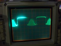
That means that the op-amp is trying to drive the top half but something in the top half of the circuit isn't allowing the drive to get to the output transistors.
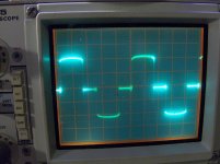
It appears that the other channels are severely underbiased or the channels are being driven to clipping but it's hard to know without the scope settings.
It appears that the other channels are severely underbiased or the channels are being driven to clipping but it's hard to know without the scope settings.
- Status
- This old topic is closed. If you want to reopen this topic, contact a moderator using the "Report Post" button.
- Home
- General Interest
- Car Audio
- Rockford Fosgate Power 650