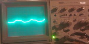
Yes. I can not get all the way to clipping just by input signal at max with gain all the way down but fairly close. The oscillation/ fuzziness was over all parts of the wave, not just the top and bottom like when the gain is increased. But also the entire wave became clear when a load was attached.
One more thing I didn't mention earlier, but the hiss we discussed earlier is related to the gain/input amplitude also, but does not go away when a load is attached like the oscillation does.
One more thing I didn't mention earlier, but the hiss we discussed earlier is related to the gain/input amplitude also, but does not go away when a load is attached like the oscillation does.
The hissing is the audio signal emanating from the board. It is only audible when a signal is input, it is also proportional to the frequency of the input signal.
I may be misunderstanding how to discern what physical part of the board/component it is emanating from, but it is heard through the tracer all the way through the audio circuit from input to output.
I may be misunderstanding how to discern what physical part of the board/component it is emanating from, but it is heard through the tracer all the way through the audio circuit from input to output.
The "hiss" is audible, but far less when music is played. When music is played it is actually music instead of a hiss. You can hear music from the board with no speakers hooked up.
I really wasn't that concerned about that anymore, unless it is indicative of something that should be fixed for reliability, since putting the amp in a vehicle, were it could not be noticed in the cabin.
I mentioned it again in #141 incase it was something related to the oscillation.
The channel with the loudest hiss/music from the board is actually the channel with very little oscillation (Ch 1).
Actually the two channels with the greatest amount of oscillation, the hiss is the least audible on.
Does the hiss change at the limits of the 12v supply voltage (10.5-16v)?
What's the gate drive waveform look like when everything is set like it was in the image above?
What's the gate drive waveform look like when everything is set like it was in the image above?
Yes the audible amplitude of the hiss is also proportionately dependent on 12V PS input voltage.
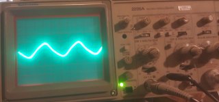
The PS gate drive is attached. I had to change the vertical scale to make it visible. Scope is set at 5 V/div and 10 us
Supply voltage is 13.54 Vdc
The PS gate drive is attached. I had to change the vertical scale to make it visible. Scope is set at 5 V/div and 10 us
Supply voltage is 13.54 Vdc
Attachments
At what 12v supply voltage do you see essentially 0v across terminals 1 and 2 of the 494?
When it reaches 0v between them, what's the DC voltage to ground on those pins?
When it reaches 0v between them, what's the DC voltage to ground on those pins?
My supply will only go to '15' Vdc, actually 14.70 Vdc.
At 14.70 V this is closest to 0 V I can get across pins 1 and 2, which is 0.607 Vdc.
To ground:
1: 2.031 Vdc
2: 2.639 Vdc
At 14.70 V this is closest to 0 V I can get across pins 1 and 2, which is 0.607 Vdc.
To ground:
1: 2.031 Vdc
2: 2.639 Vdc
Pin 3 is mainly noise. If you ground the scope probe with a short lead to pin 7 of the 494, the signal will be cleaner. It's not that it's really noisy but at .2v/div, it's going to look noisy.
The other waveform looks OK, in general but I don't know precisely what point it was taken from.
The other waveform looks OK, in general but I don't know precisely what point it was taken from.
Yes sir, in the circuit.
With the oscillation, should I just let my son use it as is?
It will be running a set of active 2-way components. The reason I ask is I remember reading either in a post or the tutorial about oscillation destroying a tweeter in seconds. Not sure if this is the type of oscillation you were speaking of.
Confirm that the amp doesn't oscillate with the load being used in the vehicle.
The small amount of oscillation you've shown isn't good but it probably wouldn't destroy a tweeter. Some forms of oscillation result in rail-rail oscillation that can destroy speakers (including tweeters)?
In some Rockford amps, using the treble boost at or near full boost AND having the gain high will result in the destructive type of oscillation. This was generally seen in the era of amps that had the large, flat potentiometers for bass and treble.
Hello Perry,
After more tinkering I did find a difference between Ch4 and the other three channels.
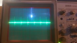
With no input signal, I found what I think would be oscillation at a frequency of 500 kHz. This only on Ch4. it is riding on +2, 0, -2 Vdc, depending on which side of the circuit with respect to the +/- rails the measurement was taken.
I am referencing page 6 of the diagram in post #117
Scope set at 1 V/div and 0.5 us
The first pic oscillation can be seen on:
Collector on Q405 and Q406
Base and Emitter Q408 and Q409
BCE on Q407
The image was actually taken on one terminal of the bias pot.
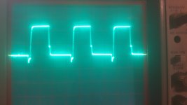
The second picture is, 1 V/div and 0.5 us, is taken on the drain of the out put FETs and can also be seen on the LR+ speaker terminal.
All the other channels show ~0 Vdc on the drains and the speaker terminals.
Before I start changing parts, does this look like anything you've seen before.
Thank you.
After more tinkering I did find a difference between Ch4 and the other three channels.
With no input signal, I found what I think would be oscillation at a frequency of 500 kHz. This only on Ch4. it is riding on +2, 0, -2 Vdc, depending on which side of the circuit with respect to the +/- rails the measurement was taken.
I am referencing page 6 of the diagram in post #117
Scope set at 1 V/div and 0.5 us
The first pic oscillation can be seen on:
Collector on Q405 and Q406
Base and Emitter Q408 and Q409
BCE on Q407
The image was actually taken on one terminal of the bias pot.
The second picture is, 1 V/div and 0.5 us, is taken on the drain of the out put FETs and can also be seen on the LR+ speaker terminal.
All the other channels show ~0 Vdc on the drains and the speaker terminals.
Before I start changing parts, does this look like anything you've seen before.
Thank you.
Attachments
Are you saying that 3 channels are absolutely perfect and that ch4 is the only channel with oscillation?
Does it go away with a load?
Do you see this on the capacitor C412?
Does it go away with a load?
Do you see this on the capacitor C412?
- Home
- General Interest
- Car Audio
- Rockford Fosgate Power 400a4