Someone tried repairing this amp before .
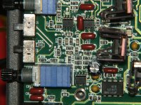
They have 10 ohm gate resistors with 3205’S installed are the 10 ohm gate resistors fine or should I use the 47 ohm ?
Also does anyone know what value C60 is ?
It sits behind the LM337 regulator
Also the value of R44 ?
It sits next to the transformer
They have 10 ohm gate resistors with 3205’S installed are the 10 ohm gate resistors fine or should I use the 47 ohm ?
Also does anyone know what value C60 is ?
It sits behind the LM337 regulator
Also the value of R44 ?
It sits next to the transformer
I leave the 10 ohm gate resistors. Some use 47. Either will work. All need to be the same value.
C60 is the same as C59, 100uF@25.
R44 is 10 ohms.
C60 is the same as C59, 100uF@25.
R44 is 10 ohms.
Do you know what the value is of the gate resistors for the outputs ?
Someone switched them all and I don’t think they are the correct value
Someone switched them all and I don’t think they are the correct value
I have also seen 22 ohm in there from the factory as well, I have also seen a mix of 15 ohm and 22 ohm from the factory.
Anyone have a schematic for this amp ?
amprepairguy@hotmail.com
I noticed someone has switched other caps in here to the wrong value and other parts as well so I’m in need of a schematic to figure this amp out since there are a lot of wrong values
amprepairguy@hotmail.com
I noticed someone has switched other caps in here to the wrong value and other parts as well so I’m in need of a schematic to figure this amp out since there are a lot of wrong values
In the schematic half the outputs have 15 ohm gate resistors the other half have 22 ohm gate resistors .
Can I use 15 ohm resistors for all of the outputs ?
Can I use 15 ohm resistors for all of the outputs ?
The 27 ohm gate resistors we’re wrong someone switched them out .
So you would suggest using 15 ohm for half the outputs and 22 ohm for the other half like the schematic says ?
So you would suggest using 15 ohm for half the outputs and 22 ohm for the other half like the schematic says ?
The loading of the drive circuit is different between the 3415s and the 6215s. Maybe the engineers had a reason to use different values... maybe it's just what the modeling told them to use. I'd use what's in the diagram unless someone has a valid reason to use something else.
Ok got the amp all back together .
Powers up and idles fine .
I get +- 12 volts on opamps and get 125 volts of rail measured directly across the black and red wires .
Amp has very low output
Any ideas on what to check ?
Powers up and idles fine .
I get +- 12 volts on opamps and get 125 volts of rail measured directly across the black and red wires .
Amp has very low output
Any ideas on what to check ?
Have you operated all pots and switches through their entire range to see if that helped?
Do you have rail-rail oscillation on the outputs?
With the gain and crossover controls fully clockwise and a low frequency drive signal (50-100Hz) of about .25v AC at the RCA jacks, what is the AC voltage at pin 1 of U4?
Do you have rail-rail oscillation on the outputs?
With the gain and crossover controls fully clockwise and a low frequency drive signal (50-100Hz) of about .25v AC at the RCA jacks, what is the AC voltage at pin 1 of U4?
Yes I operated all switches and pots through the entire range .
I have rail to rail oscillation on the outputs .
On pin 1 of U4 I get 0.80 volts ac
I have rail to rail oscillation on the outputs .
On pin 1 of U4 I get 0.80 volts ac
This is what I have on an amp here.
At 0.23v at the RCAs...
0.419v AC at pin 1 of U4
4.32v AC on pin 6 of U17
4.18v AC on pin 2 of U8
All of the above are audio, approximately RMS
On pin 3 of U8...
The 91k triangle waveform that swings about ±5.2v.
This gets a BD1000 just to clipping, no load.
At 0.23v at the RCAs...
0.419v AC at pin 1 of U4
4.32v AC on pin 6 of U17
4.18v AC on pin 2 of U8
All of the above are audio, approximately RMS
On pin 3 of U8...
The 91k triangle waveform that swings about ±5.2v.
This gets a BD1000 just to clipping, no load.
I see the problem .
The whole preamp section has to be rebuilt .
Someone switched all of the values of the resistors in it so none of them match the schematic
The whole preamp section has to be rebuilt .
Someone switched all of the values of the resistors in it so none of them match the schematic
Anyone have a high res pic of the preamp section in this amp ?
Wanna make sure the schematic is right since there are different value resistors and there are caps missing in this amp
Wanna make sure the schematic is right since there are different value resistors and there are caps missing in this amp
- Status
- Not open for further replies.
- Home
- General Interest
- Car Audio
- Rockford Fosgate Power 1501BD