Monitor the DC voltage on pin 2 of either IC14 or IC15. Connect the meter to the pin before you apply remote and monitor the voltage for several seconds after you apply remote voltage. What does the voltage do (rise, fall, pulse...)?
Would it be possible to lift pin 2 from the board?
Would it be possible to lift pin 2 from the board?
Upon connecting remote, the CSD-line (which is common at pin 2 to both IC14 and IC15 as well as R66 (100kOhm)), voltage rises quickly (20ms) to approx 1.162V. Then stays there forever..
Using a scope reveals the same (perfectly linear readout).
Releasing remote causes voltage to drop instantaneously to 400mV then slowly discharging something to 0V during the next 50 seconds.
Thats pretty much it..
It's possible to lift pin 2 from the board, yes.
Using a scope reveals the same (perfectly linear readout).
Releasing remote causes voltage to drop instantaneously to 400mV then slowly discharging something to 0V during the next 50 seconds.
Thats pretty much it..
It's possible to lift pin 2 from the board, yes.
Lift pin 2 on both ICs to see if either/both rise significantly higher. I 'think' this should be safe but I've never tried it.
Did the output stage produce rail-rail oscillation?
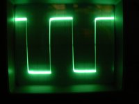
Do you have a square wave on the input pin of IC14 and IC15?
Did you notice any other changes?
Do you have a square wave on the input pin of IC14 and IC15?
Did you notice any other changes?
No rail-rail oscillation (L101/L201) and no square wave on pin 3 of neither IC14 or IC15. They "idle" at 358mV though.
No other changes were observed.
No other changes were observed.
IC12 DC voltages (with pin 2 still lifted from IC14 & 15):
Pin 1: 0.218
Pin 2: 5.69
Pin 3: 0.44
Pin 4: 0
Pin 5: 3.59
Pin 6: 5.69
Pin 7: 0
Pin 8: 11.39
Pin 1: 0.218
Pin 2: 5.69
Pin 3: 0.44
Pin 4: 0
Pin 5: 3.59
Pin 6: 5.69
Pin 7: 0
Pin 8: 11.39
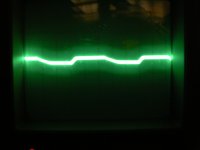
I would have expected a triangle waveform on the capacitor side.
I have another Rockford amp coming later today or tomorrow that may use a similar circuit. I'm going to wait for that before I ask for anything else on this amp.
I have another Rockford amp coming later today or tomorrow that may use a similar circuit. I'm going to wait for that before I ask for anything else on this amp.
Update:
I've not got RED light.
IC12 (LM393) was faulty.
200kOhms between pin 5 and pin 4 kept the output low at pin 7 preventing CSD-line to go high. It's now approx 10V and the triangle shaped waveform you expected at the capacitor side is now present.
However: still no sound... :-(
Feeding 400Hz at the RCA's can be followed all the way to IC10 (TL072) pins 3 and 5.
36V between pin 4 and 8.
Nothing at pin 1 or 7 though..
Should I try replacing IC10 once more?
Replaced both IC10 (TL072) and IC11 (LM393). Same story: amp idles but no sound. No protect.
Feeding RCA's with a 400Hz sinus signal. This can be found (amplified) on both pin 2 and 3 as well as pin 5 and 6 on IC10. No output on pins 1 or 7 though. 36,22V between pin 4 and 8. 21V at pin 2, 3, 5 and 6. 12,93V at pin 1 and 7.
IC11 got a sawtooth shaped waveform on leg 5 and 3 (fed from the PWM-circuit). This signal is 4.2Vpp.
Latest readings for IC11:
1: 0.326
2: 11.16
3: 1.171
4: 0
5: 1.171
6: 11.16
7: 0.331
8: 36.1
Latest readings for IC12:
1: 1.197
2: 5.75
3: 9.32
4: 0
5: 11.69
6: 5.75
7: 11.5
8: 11.5
Also: with IC10 removed from the board, poking around with my finger touching various pins on IC11, both "digitized" and analog 50Hz noise could be heared from the speaker (weak but audible).
What am I missing here?
Could anyone point me in any direction for where to proceed trouble shooting this demonized thing?
Attachments
Do you have rail-rail oscillation on the output transistors?
What is the DC voltage on both terminals of L101 and L201 (4 voltages)?
What is the DC voltage on both terminals of L101 and L201 (4 voltages)?
The reason that the output of the op-amps has higher voltage than the input is because it is trying to get the output voltage higher.
I'm not really familiar with these driver ICs but from what I read, the CSD pin is pulsed low and then allowed to rise toward the supply voltage (13v). If you place the scope probe on the CSD pin before applying remote voltage, do you see the pulse towards ground and then the voltage rising on the CSD pin?
I'm not really familiar with these driver ICs but from what I read, the CSD pin is pulsed low and then allowed to rise toward the supply voltage (13v). If you place the scope probe on the CSD pin before applying remote voltage, do you see the pulse towards ground and then the voltage rising on the CSD pin?
Probe on pin 2 (CSD) while connecting B+ and ground: voltage drops to -7.0mV.
At the instant remote is applied, yellow LED's are lit and CSD voltage rises to 770mV.
Then after exactly 1 second, red LED's are lit and CSD voltage rises to 10.15V.
Removing remote makes CSD voltage to drop instant to approx 400mV, then it keeps falling back to the initial -7mV.
Measures made by both DMM and scope. Strictly linear readout, no pulses.
Do we suspect IC14 and 15 to have flaws?
As mentioned above: with IC10 removed from the board I actually made the amp produce some "sound" to the speaker. Not my favourite track though, but it makes me think those driver IC's are OK, just not fed with the right "stuff"...
- Status
- Not open for further replies.
- Home
- General Interest
- Car Audio
- Rockford Fosgate P1000X1D stuck in protect