Hey guys,
I am working on a bd1000 and have 36v on the speaker output. I replace the powersupply fets and the output fets. I also had to replace one of the ic drivers
MIC4420CT cause it was shorted. Amp powers up fine, only thing i noticed out of the ordinary was using diode check on my meter from (+) on source and (-) on drain it read correct around .498 vdc. When i reversed the leads it would read a short 0.000vdc. I think this causing my problem not sure if the fets are leaking or if there is a bad component somewhere else.
Some meters won't read correctly if there is voltage present in the circuit. Charged capacitors can provide enough voltage to cause this problem. I'm guessing that this isn't a Fluke meter.
Post the DC voltage on all pins of U17.
Post the DC voltage on all pins of U17.
Damn your. Good ..and yes its not a fluke..
Pins
1= nc
2= 0.021
3= 0.002
4= -9.70
5= nc
6= 9.88
7=0.006
8=nc
Pins
1= nc
2= 0.021
3= 0.002
4= -9.70
5= nc
6= 9.88
7=0.006
8=nc
Something doesn't seem right. You have positive output on pin 6 but no supply voltage on pin 7. Re-check the voltage.
Is the voltage on the positive speaker terminal positive or negative 36v?
Is the voltage on the positive speaker terminal positive or negative 36v?
Perry,
My mistake reading the pin-out of the chip wrong..
6= 0.006
7= 9.88
the output on the speaker terminal is +5.025vdc this morning. At one point i noticed the protect light was on and the output on the speaker terminals was 0.00vdc and the output pin 6 on u17 was 8.58 vdc. Pin 2 was 1.021vdc. I removed power and it went back to normal mode and was reading 5vdc on speaker terminal.
Those look OK.
Can you power it up and down a few more times, posting the voltage on pins 2 and 6 of U17 as well as the DC on the output?
The voltage on U17 is inconclusive. It appears that it could possibly be defective but with only about 20mv difference between the two inputs, it's hard to tell.
Can you power it up and down a few more times, posting the voltage on pins 2 and 6 of U17 as well as the DC on the output?
The voltage on U17 is inconclusive. It appears that it could possibly be defective but with only about 20mv difference between the two inputs, it's hard to tell.
Perry the pin voltages were about the same. Although, i did notice the voltage on speaker terminal would start to increase to 4.35v and when power is removed it immediately drops to .678 volts. The voltage is not very stable and tends to bounce from 4v to 4.38v.
Just to confirm... The protect LED is on for a few seconds after remote voltage is applied, then goes off. Is that correct?
Perry the protect LED stays on for about 2-3 seconds. During this period the speaker terminal voltage reads 0.000v and once the protect LED light goes off the voltage starts to slowly climb. I also, just notice that the resistor on R44 gets extremely hot but can't remember if it is suspposed to be that hot or no.
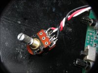
Yes... what is the purpose of attaching the pot to this chip. What is the function of this chip?
This chip monitors the output and drives the outputs (or actually the drive circuit which in-turn drives the outputs) so that there is no (or very little) distortion in the output signal.
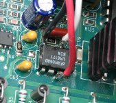
In the photo, you can see that R35 and R31 have been disconnected. You can leave R35 but you need to slide R31 from its pads.
What you will need to do is rotate the pot from about the 10 o'clock position to the 2 o'clock position to make the output of the output of U17 toggle from 9v to -9v. Go through the 12 o'clock position quickly. Sometimes, if you go through it slowly, it can damage the outputs. Try not to go below the 9 o'clock or above the 3 o'clock positions.
First, confirm that pin 6 is toggling as it should when you go from 10 to 2.
The pot needs to be at least 4.7k ohms. A 10k is better. Anything up to 100k should work.
Perry,
all i had was a 20k pot like the ones used for the crossover. I wired it like the picture and powered the unit up. i checked the output on pin 6 and it was reading 8.68v with 123v on the speaker terminal. When i turned the pot from 10 o'clock to 2 o'clock the reading changed to a -8.08v.
all i had was a 20k pot like the ones used for the crossover. I wired it like the picture and powered the unit up. i checked the output on pin 6 and it was reading 8.68v with 123v on the speaker terminal. When i turned the pot from 10 o'clock to 2 o'clock the reading changed to a -8.08v.
Where was the -8v? on the speaker terminals or on pin 6?
If on pin 6, did the voltage on the outputs go to approximately negative 120v?
If on pin 6, did the voltage on the outputs go to approximately negative 120v?
That seems to indicate that the drive circuit is OK. I'd suggest replacing U17. Don't forget to reinstall R31.
If you work on these amps often, you will find this test useful.
If you work on these amps often, you will find this test useful.
Perry i will replace U17 and seem if that fixes the voltage on the speaker terminals. I have about 26 more rockford amps to fix in my spare time. Just wondering if you own your shop, if so how do you find time to help everyone with there repairs? You definitely love what you do.
- Status
- Not open for further replies.
- Home
- General Interest
- Car Audio
- Rockford Fosgate BD1000@1