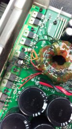
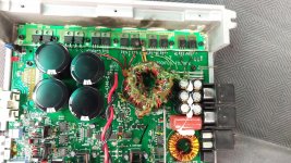
Ok So i fiqured out how to make my own thread (thanks Perry) Years of computer knowledge and i couldnt find it.?? Anyway i have two rockford amplifiers which had blown out tc18 on both amp same fet? Same person owned both amps, no other eye level noticable damage to the boards, i just want to replace every mosfet on both rails and start fresh on both amps, but i want to make sure that there isnt further damage. So i used what i beleived to be good diodes from both amps to soder on to one board, still no power except on the fets is 10v. when i tested the twisted pair of wires nothing.
When you refer to the components, use the circuit board designations printed on the board.
If you don't have to replace the output transistors (other side of the amp), don't do anything with them.
For the output transistors, you should not read anything near 0 ohms between the legs of any individual transistor in any terminal/probe combination. Check them.
Have you ever replaced the transistors on the MEHSA insulators like those used in this amp?
Yes I have a heat gun, that's how I have done them in the past. So no need to mess with any on the other rail? Or the 1520's? I was just wondering what gets are supposed to be on the rail there is three different ones. 75n06 and I think 3105? Not home at the min. I just want to put what originally went on it.
If there are no shorted output transistors, all you should need to replace is the power supply FETs (I'd use the IRF3205), the gate resistors and the driver transistors (if they failed).
So the rest of the boaard is super clean and the other side is fine, what should i get when i test them? Or just replace all of them? i have IRF3205's here somewhere already from some amp i did before i should have enough.
Also the outputs do have a reading of all the same 9.76-9.81??? Hooked to the board, the rail i have unhooked i dont get a reading from any of them.
#8 doesn't mean much without knowing the probe placement or meter mode. If none were shorted, they're likely OK.
Remove the obviously blown PS FET and check the rest. It's likely that they're shorted but if they're not, you can check a few other things before replacing all of them.
Remove the obviously blown PS FET and check the rest. It's likely that they're shorted but if they're not, you can check a few other things before replacing all of them.
So I replaced just the blown fet and still nothing when I added power, no smoke, just no lights or power on the board. Should I test them for voltage while power is connected, or just the twisted pair of wires,? I didn't get any voltage on the wires
So when i put all the new fets on the power side and plug it up it make a crackle and damaged the battery.?
and i think it damaged the same fet. and yes they were bad i think. I couldnt really tell. so i just changed them all to be safe.
If you want/need help, you need to be patient.
If the drive circuit was not intact, changing all of the FETs could result in all being blown.
Connect only remote and ground and measure the DC voltage on all 8 FETs. Post the voltages along with the circuit board designations (not the TC #s) for the individual FETs.
If the drive circuit was not intact, changing all of the FETs could result in all being blown.
Connect only remote and ground and measure the DC voltage on all 8 FETs. Post the voltages along with the circuit board designations (not the TC #s) for the individual FETs.
Will do perry. thanks ill will absolutely wait for your advice from here out, i have replaced fets before but other than that it is beyond me.
Ok So i did what you said and got these volts:
Q6 8.64
Q5 8.63
Q7 8.64
Q8 0.86
Q12 ZERO
Q11 ZERO
Q10 ZERO
Q9 ZERO
Q6 8.64
Q5 8.63
Q7 8.64
Q8 0.86
Q12 ZERO
Q11 ZERO
Q10 ZERO
Q9 ZERO
Last edited:
Q6-8 likely have a blown PNP driver transistor.
Q8 appears to have an open gate resistor.
Q9-12 appear to have two blown driver transistors.
You will need to replace all 4 driver transistors and all open or out of tolerance gate resistors.
Pull the 4 driver transistors and check the resistance between the gate leg and the other two legs. They should read infinite resistance with the drivers out of the circuit. If they do not, post the resistance read across the FET along with its circuit board designation.
Do NOT connect B+ again until told to do so.
- Status
- Not open for further replies.
- Home
- General Interest
- Car Audio
- Rockford Fosgate 1001bd Repair Help