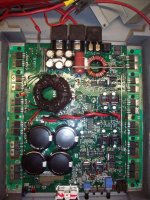
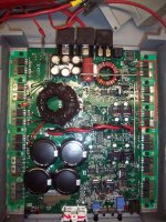
Fosgate BD1001 amp, blows fuses, No obvious issues upon opening, using a circuit breaker to test at 30 amps, hearing a whistling noise and circuit breaker trips, could not locate source of whistling noise, Pulled board from chassis noticed flux melted where torroid? coil is soldered to board, also the 6 filter caps get very hot with only a the few seconds it stays on before tripping the breaker, also noticed only one side of amp is getting warm after several cycles, other side remains cold. i have included pictures, side that remains cool is has continuity through all legs and of adjacent fets, I think i am going to have to desolder these and find the one that is bad, Thank you in advance for your help,
Attachments
Measure from gate to source on the outputs with your meter and tell me what the readings are.
You may have shorted outputs, or a bad op-amp causing the squeeling. Some of the old BD amps had a whine to them because of toroid vibration.
You may have shorted outputs, or a bad op-amp causing the squeeling. Some of the old BD amps had a whine to them because of toroid vibration.
they are all closed switch on the ones in question, all the Fets with the solder in the middle. there are 6, i can take any pin on any one of these and get continuity on any pin of any of the others, I'm not sure how all 3 legs can be shorted, so i suspect something upstream, but don't know what. i do not have a schematic. all of the other outputs test the same, readings were consistent, with the exception of the 6 mentioned.
Hi,
Those six FET correspond to the audio output, you must remove them from the motherboard, and check them one by one to know, how many of them have failed,, anyway, most likely, it is that you have to replace them all.
Those six FET correspond to the audio output, you must remove them from the motherboard, and check them one by one to know, how many of them have failed,, anyway, most likely, it is that you have to replace them all.
yes, i think i will proceed with that, anyone know where I can find a schematic on this amp, i have searched all over using google. Thank you
I'm going to reply here instead of via email so others might benefit from the information.
Notes:
A 30 amp breaker is virtually useless to help protect the amp from damage. It takes far more than the rated current to open a breaker quickly enough to protect an amp.
The MEHSA insulator that you emailed me about will have to be replaced. Sean may have one. If not, you may have to make a clamp and mount them like most other amps.
If you would have measured the resistance as Sean recommended, you could have cut out the defective FETs to and checked the drive circuit. If it would have been OK, you could have removed the defective FETs and powered it up to check other functions.
You would have to replace all 6 of the FETs working together and any blown driver components to fully repair the amp.
'Continuity' is useless when checking semiconductors. Continuity could simply mean that the component isn't open. When checking, you need to set the meter to ohms or diode-check and post the exact readings including the units displayed.
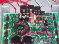
The FETs you have in the rectangle are 1/2 of the FETs in the audio circuit and are responsible for switching the rail voltage up or down. The other 6 on that side of the amp generate the PWM signal for the audio output. The power supply FETs are on the other side of the amp.
Notes:
A 30 amp breaker is virtually useless to help protect the amp from damage. It takes far more than the rated current to open a breaker quickly enough to protect an amp.
The MEHSA insulator that you emailed me about will have to be replaced. Sean may have one. If not, you may have to make a clamp and mount them like most other amps.
If you would have measured the resistance as Sean recommended, you could have cut out the defective FETs to and checked the drive circuit. If it would have been OK, you could have removed the defective FETs and powered it up to check other functions.
You would have to replace all 6 of the FETs working together and any blown driver components to fully repair the amp.
'Continuity' is useless when checking semiconductors. Continuity could simply mean that the component isn't open. When checking, you need to set the meter to ohms or diode-check and post the exact readings including the units displayed.
The FETs you have in the rectangle are 1/2 of the FETs in the audio circuit and are responsible for switching the rail voltage up or down. The other 6 on that side of the amp generate the PWM signal for the audio output. The power supply FETs are on the other side of the amp.
Thank you very much, i really appreciate your help on this, I thought the rated current on this amp was 100 amps? what size breaker should i use? the voltages i should have taken were zero or totally closed on the diode check on my meter, Much like just holding the two probes to each other. i found at least 4 of these to be shorted across all three legs, is that weird? the insulator is not damaged all the way to the the metal back, still no good? Thanks again.
In the circuit, the gate resistors would have caused the ones that were not shorted to read slightly higher. That would have indicated that they were still OK and could be left in the circuit to allow for further testing.
If the insulator is damaged, the FETs won't cool at the same rate and that will lead to unequal load sharing and the amp will be unreliable.
When testing an amp that you suspect is defective, it's typically better to use a small fuse or a current limiter but that's only after you check all of the heatsink mounted components to see if any are shorted. The following datasheet shows that a breaker can take more than 20 seconds to trip at 2x it's rated current. It can take several seconds to trip at 5x it's rated current.
http://www1.cooperbussmann.com/pdf/d698bc45-120e-47ae-9375-ebf1cda0ad62.pdf
wow, thanks, i guess i will use a current limiter. I read that i can use a headlight as a limiter? is that correct? I will replace these fets as well and get back to you. I'm trying to hunt down an insulator strip.
You can't replace them without checking the drive circuit (unless you want to risk blowing the FETs).
A headlamp will work. If you have a local radio shack, buy 4 of the 8 ohm 20 watt resistors and connect them in parallel.
Have you decided what you're going to do about the insulator?
A headlamp will work. If you have a local radio shack, buy 4 of the 8 ohm 20 watt resistors and connect them in parallel.
Have you decided what you're going to do about the insulator?
I messaged Sean about the insulator as you hinted he may have one, I have not heard back. not sure how to check the dive circuit
If you don't have a current limiter, you should insert a 15 amp fuse in the B+ line when testing.
Do you only have the 6 FETs in the rectangle out of the amp?
You will need to discharge the rail caps and then desolder the red and black twisted wires from the power supply side of the amp. Then clean up the solder pads (top and bottom of the board) and make sure that there are no solder bridges between them.
Also make sure that there are no solder bridges between the solder pads for the FETs that you removed.
You'll need to solder a wire bridge between pins 2 and 6 of U17.
Do you have a scope? If not, can you borrow one?
Please can I ask where one can get the electronic parts to repair this amp, I'm in South Africa and not sure if I should really start a new thread to ask this question. I heard that International Rectifier Parts would be compatible but nobody i came across so far could find a supplier in South Africa? I have the identical amp.
- Status
- Not open for further replies.
- Home
- General Interest
- Car Audio
- Rockford fosgate 1001BD Help