I think the problem is the missing C8.
Try reinstalling it and confirm that's back to what it was.
What did you use for drivers?
What was the complete part number for the 3205s?
Try reinstalling it and confirm that's back to what it was.
What did you use for drivers?
What was the complete part number for the 3205s?
I have to call it quits for tonight. I'll pop C8 back in and test tomorrow.
The drivers are MMBTA06LT1G and MMBTA56LT1G
They are marked 1GM and 2 GM respectively, the same as the parts I removed.
Board locations Q1 Q2 Q3 Q4
The 3205s are:
IRF3205PBF
They came from either Mouser or Arrow, same for the drivers.
The drivers are MMBTA06LT1G and MMBTA56LT1G
They are marked 1GM and 2 GM respectively, the same as the parts I removed.
Board locations Q1 Q2 Q3 Q4
The 3205s are:
IRF3205PBF
They came from either Mouser or Arrow, same for the drivers.
I've finally been able to set my work area back up after having to temporarily repurpose the space.
I spent some time refamiliarizing myself with the board and made the following observations while to adjusting the bias.
Channel 1: the voltage across the source resistor gradually rises as I turn the bias pot CW and gradually drops as I turn the bias pot CCW.
Channel 2: the voltage across the source resistor jumps from 0.0mv to 1.2mv about half way between full CCW and full CC. As I turn the pot back down (CCW) the voltage stays constant until near fully CCW then drops to zero. *On occasion it will act the same as ch 2 and 3. I can't reliably reproduce this behavior and suspect it's temperature dependant.*
Channel 3: the voltage across the source resistor jumps from 0.0mv to 2.1mv about half way between full CCW and full CC. As I turn the pot back down (CCW) the voltage gradually increase to 2.4mv at full CCW. Periodically, continuing to turn the pot CC will cause the voltage to decrease then start increasing again. Removing and re-applying the remote signal resets the voltage across the resistor until the bias pot is adjusted to roughly the half way point again.
Channel 4: the voltage across the source resistor jumps from 0.0mv to 1.7mv about half way between full CCW and full CC. As I turn the pot back down (CCW) the voltage gradually increase to 2.4mv at full CCW. Periodically, continuing to turn the pot CC will cause the voltage to decrease then start increasing again. Removing and re-applying the remote signal resets the voltage across the resistor until the bias pot is adjusted to roughly the half way point again.
Notes:
•The above voltages were measured across the source resistors on negative rail.
•The board has every component back in its proper place.
•The voltages listed for channels 3 and 4 fluctuate based on temperature. The hotter the components the higher the voltage.
•The bias potentiometers appear to be functioning correctly with the resistance gradually increasing and decreasing as the wiper moves across the resistive element.
•I have swapped the following parts back and forth between channels 1 and 2 trying to isolate the problem with no luck: output transistors (irf540 & irf9540) | transistors Q107/Q207 (mps6521) | and Q108/Q208 Q109/Q209 (mpsa06 and mpsa56)
Any ideas what's going on? I'm sure it's abundantly clear I'm way out of my depth here.
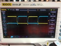
Do all channels produce clean audio (driving a load) up to clipping?
Do the top and bottom of the waveforms clip symmetrically?
Do the top and bottom of the waveforms clip symmetrically?
As near as I can tell, yes.
With no gain pots the only way I can test is by raising and lowering the head unit volume which isn't as granular as I'd like. All channels produce a clean sine wave (125 hz) at a volume of 30 and have both the top and bottom edges slightly clipped at volume 31. The HU output is clean all the way to max volume- 35.
I do not see the "crossover distortion" that the bias is supposed to correct, but I've also never been able capture it on the scope.
The load is an array of resistors with a final resistance of 47 ohms.
If you adjust the bias by using the amp meter on your 12v power supply, does the bias ramp up smoothly for each channel?
Amplifiers don't necessarily need any bias current to be distortion free. Some amps have the range to allow distortion to be seen but that's rare and the distortion is more likely to be seen at high frequencies.
Amplifiers don't necessarily need any bias current to be distortion free. Some amps have the range to allow distortion to be seen but that's rare and the distortion is more likely to be seen at high frequencies.
Channel 1: the current increases as the pot is turned CC and decreases as the pot is turned CCW
Channels 2, 3 and 4: the current jumps slightly as the pot reaches about the mid point. Once it has jumped turning the pot back to full CCW increases the current draw. Turning back toward the middle, the current drops till about the mid point where it rapidly starts increasing.
Basically the same behavior as measuring across the source resistors, just a different measurement.
Yes sir, they've had a thorough soak of deoxit d100 with many minutes of rotation. I've done that twice with plenty of time for it to penetrate (weeks.) I can't be certain they are OK but the resistance changes smoothly as I move the wipers over their entire range.
Can you move the pot that's acting normally to a bad channel to be absolutely sure that the pots are not an issue?
I'll certainly give it a go. I've avoided doing it till now since I likely destroyed one of the gain pots with the iron. One of the big distributors does carry similar replacements.
Swapped the pots between channel 1 and channel 4, no change. Ch. 1 still biases normally and ch. 4 still has a jump in current about half way through the rotation.
Edit: and yes I used the amazing chip-Quik
Edit: and yes I used the amazing chip-Quik
If you reduce the 12v supply voltage so that the amp supply remains at full duty cycle, does that make a difference?
How is the drive voltage changing when there is no change there?
Does the amp draw more/less current as the drive voltage changes?
Go higher than 14v to see if the duty cycle drops. I think it should happen at about ±33v.
Does the amp draw more/less current as the drive voltage changes?
Go higher than 14v to see if the duty cycle drops. I think it should happen at about ±33v.
- Home
- General Interest
- Car Audio
- Rockford 400a4