Hello,
I have just purchased a pre-built JHL amp board and a transformer to go with it, and I am looking for a bit of a sanity check whilst I wait for it to arrive to plan how I am going to connect things.
This is the transformer: 30W 220V R Core Transformer 9V 2 15V 2 Free Shipping | eBay
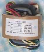
The mains side is straight forward, One to neutral, one to active, (both are red so it doesn't appear to matter which one), and grn/yel to Protective earth. So far so good.
My question really revolves around the output side. I need a 15-0-15 ac supply. My first instinct is that I take each of the yellows as a +15 and the red attached to neutral as "0". Is this correct, or do I need to take one green and one yellow as my +15's?
Is there any benefit to me putting an appropriately sized capacitor bank between the output of the transformer, and the input to the amp? Space in the enclosure isn't a problem, but if there is likely to be no benefit I wont bother!
If you could please let me know if my interpretation of the transformer is correct it would be really appreciated!
I have just purchased a pre-built JHL amp board and a transformer to go with it, and I am looking for a bit of a sanity check whilst I wait for it to arrive to plan how I am going to connect things.
This is the transformer: 30W 220V R Core Transformer 9V 2 15V 2 Free Shipping | eBay
The mains side is straight forward, One to neutral, one to active, (both are red so it doesn't appear to matter which one), and grn/yel to Protective earth. So far so good.
My question really revolves around the output side. I need a 15-0-15 ac supply. My first instinct is that I take each of the yellows as a +15 and the red attached to neutral as "0". Is this correct, or do I need to take one green and one yellow as my +15's?
Is there any benefit to me putting an appropriately sized capacitor bank between the output of the transformer, and the input to the amp? Space in the enclosure isn't a problem, but if there is likely to be no benefit I wont bother!
If you could please let me know if my interpretation of the transformer is correct it would be really appreciated!
Attachments
OK. Looking at pictures of these installed in finished kits, my assumptions with the outputs are clearly wrong.
Can anyone point me to a document / website / whitepaper so that I can learn how this should be wired?
Can anyone point me to a document / website / whitepaper so that I can learn how this should be wired?
ok.
Lets see if I got this right now....
To get the output I need, I would connect one yellow as +15, one green as +15, and the remaining yellow and green would connect together to get my 0.
Is this correct?
Lets see if I got this right now....
To get the output I need, I would connect one yellow as +15, one green as +15, and the remaining yellow and green would connect together to get my 0.
Is this correct?
Yes.
Keep the reds (mains primary) well away from the secondaries. The green/yellow striped wire (screen) should attach to the grounded chassis. You should also make a connection between chassis and the circuit 0V point, but possibly not your green+yellow junction - read threads on grounding to avoid hum.
Keep the reds (mains primary) well away from the secondaries. The green/yellow striped wire (screen) should attach to the grounded chassis. You should also make a connection between chassis and the circuit 0V point, but possibly not your green+yellow junction - read threads on grounding to avoid hum.
- Status
- Not open for further replies.