
take a few more photos before closing the lid
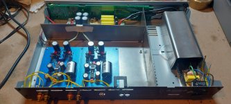
I decided to use OPA1611 (not shown in the pics) with MUSES03
very satisfied with this combination, both sound and look.
(I'm using ortofon mc quitet black s which is also ’black‘)


I decided to use OPA1611 (not shown in the pics) with MUSES03
very satisfied with this combination, both sound and look.
(I'm using ortofon mc quitet black s which is also ’black‘)
Last edited:
It has been a while....
But now I finished the project.
PS - I don't how the current shipping situation is. I still have some PCB's on stock, willing to send out to countries where RJM has problems to deliver.
But now I finished the project.
PS - I don't how the current shipping situation is. I still have some PCB's on stock, willing to send out to countries where RJM has problems to deliver.
Attachments


@EoA
Thank you for the service. Very recently, it seems like JapanPost has finally flipped the switch and enabled airmail shipping again to all major European countries. At last, we are free of Covid legacy.
While I love your casework and build overall, the wannabe graphic designer in me feels there's a missed opportunity: I would have used an IEC socket with a built-in switch for the power supply so the front panel is clean, then I would have put the Jolly Roger identically on both faceplates, without additional lettering. "Emerald", "Emerald P/S" etc. could be moved to the back.
Your font choice for "EMERALD" on each panel is .... questionable.🤔
Many thanks for the info -- will experiment!@ssmith i just tried to put some caps in psu and found that 1000uf did not help, but when I put 5600uf or 10000uf, it both sounds better in my system.
Hi Richard;
I'm looking to build the emerald phono amp in a couple of weeks. BTW, I have some opa1641 opamps in my hands. Is it applicable to use them on your phono?
Thanks in adavance.
I'm looking to build the emerald phono amp in a couple of weeks. BTW, I have some opa1641 opamps in my hands. Is it applicable to use them on your phono?
Thanks in adavance.
Thanks a lot.
What about the fet input type like opa1655?
EDIT: I found an answer for this question. Disregard, please.
What about the fet input type like opa1655?
EDIT: I found an answer for this question. Disregard, please.
Richard;
I found your answer "Note that JFET input types like the 03 have too much voltage offset to be used as the input of the Emerald when running with MC gain. As the second stage it should work, or both if you run it at MM gain."
So, if I use the emerald only for MM cart., then there is no problem w/opa1641, isn't there?
The DC gain is 10 times higher than the midband gain, so you are looking at 1000x for MM and 10,000x for MC, nominally. Let's say 0.5 V output offset is your max. acceptable value, that pegs the maximum acceptable input offset of IC1 as 500 uV and 50 uV respectively.
The datasheet value for the OPA1655 is +/-500 uV typ, +/-1 mV max. So just about okay for MM, yes.
The datasheet value for the OPA1641 is +/- 1 mV typ, +/-3.5 mV max. So not viable, even for MM, unless you carefully pre-select ICs to find ones with especially low offset values.
The datasheet value for the OPA1655 is +/-500 uV typ, +/-1 mV max. So just about okay for MM, yes.
The datasheet value for the OPA1641 is +/- 1 mV typ, +/-3.5 mV max. So not viable, even for MM, unless you carefully pre-select ICs to find ones with especially low offset values.
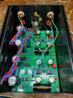
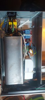
My construction. Pictures don’t show the last touches but these are details.
Box is taken from old tuner Myryad Z130.
Power and led managed by bistabile electronic switch.
2 laptop PSUs, LCLCL filter with various capacitances and types, noise at the end is reduded to a couple uV.
Schematics slightly tuned.
PCB is completely redesigned, audio connections far from supply, separate masses for each section joined in 1 point, short paths. 2nd layer of PCB is just a screen, connected in 1 point so not transferring any currents. Everything surrounded by extra mass path (next screen).
Lots of steel for extra shielding. Radiators on opamps. Grounding without any loops. PCB painted with epoxy base and metallic spray 😉 Steel, steel and more steel 😉
Carefuly selected parts etc.
No noise or hum at any volume level.
It plays with Sony PS-X65 and AT VM95ML. The sounds is warm, though dynamic and detailed.
I planned it but being satisfied with the result I didn't try tantal capacitors in supplying opamps, any experience?
Cheers
Attachments

I'm just wondering if using OPA37 instead of OPA27 would bring any benefit, after all OPA37 is optimized for high gains (even datasheet suggests using OPA37 for RIAA) but is the difference noticable? Has anyone tried other opamps in Emerald project?
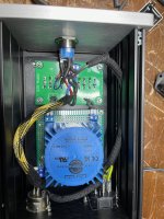
I am thinking about making a motherboard for my Emeralds.
Is there a reason to not do this aside from it being silly? The stated purpose to make a neater build but I'm really just having a lot of fun in KiCad.
Are the separations of the ground plane for power and audio useful at all? Emerald has one ground plane with the audio ground all on one side of the power ground whereas here audio ground is on either side of power ground, so I was thinking some separation and a jumper may be helpful.
@cibo
This seems to be a solution in search of a problem, though there are no obvious downsides that I can see.
I was limited to 80x100 mm boards by the free software I was using. Also, two small boards are more versatile to position than one large one.
The physical separation between this "motherboard" and the Emerald boards would be too great for the ground places to do much vs. the common ground of the metal chassis.
I would suggest your approach would be more useful if the larger board had the RCA jacks, ground lug, and power supply diodes on it, so essentially all the hardware was on it and you'd design it to fit into a particular chassis. But then, why not just put the emerald circuits on that board rather than separate daughterboards?
Hi Richard ...
First of all, thank you for so many years sharing your work, especially for the excellent support and your permanent kindness with anyone who needs your help.
Because I do not post in the forums it is not currently possible to send you messages by private, so I would like to know if it is possible that you can initiate a conversation with me to be able to consult some doubts in relation to Emerald.
I'll look forward for your answer.
- Home
- Source & Line
- Analogue Source
- RJM Audio Emerald Phono Stage Help Desk