I am thinking off adding a 5 to 10 pf bandwidth limit cap to feedback what do you think? At r5
Last edited:
Putting a cap there is worth trying in the spirit of experimentation.
Modifications of this nature are trial-and-error. In principle it should improve the stability of the input stage, but increase noise and distortion at high frequencies.
Now that you mention it, it might actually be useful, at least for the MM setting where the input IC is operating with high bandwidth.
Please let us know if you try it.
Last edited:
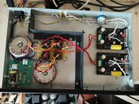
Thank you Richard for your excellent design and board production but most of all for the documentation and support. Very easy build and the end result is playing beautifully. My only mistake was connecting input to output and vice versa, which caused a few frowning looks until I hooked up the scope. I went with separate power supplies (I had the toroid spare) and repurposed an old case for a failed dab radio.
I'm letting it run in and my ears get used to it before I try anything.
- loading for the Koetsu (currently 100R)
- might increase the gain a little
- output caps
I'm letting it run in and my ears get used to it before I try anything.
- loading for the Koetsu (currently 100R)
- might increase the gain a little
- output caps
Attachments
Are there any test points where one could measure load once the unit is assembled?I'd like to measure the unit with the switchboard in different settings with and without the jumpers.
TIA
TIA
@RhythMick Thanks for the feedback and for posting a photo of your build!
@WntrMute2 You don't want to be sticking a voltmeter across the input with the unit powered up. I would remove IC1 as a precaution and have the power off. Then just measure between center and shield of the input RCA. Of make a little cable with RCA plug on one side and test leads on the other which you connect to the meter.
@WntrMute2 You don't want to be sticking a voltmeter across the input with the unit powered up. I would remove IC1 as a precaution and have the power off. Then just measure between center and shield of the input RCA. Of make a little cable with RCA plug on one side and test leads on the other which you connect to the meter.
RhythMick, that's a great-looking build. Should sound great teamed up with your Koetsu!
Why thank you kind sir. I'm still a newbie really, certainly with SS anyway.
At first I got a lot of noise when the SME motor was starting up, then I realised I hadn't attached SME pin 3 (chassis ground) to the preamp earth post, which killed it.
I was very pleased to find I had EXACTLY the right size and shape steel bracket to bend into shape as the divider. See, dear, THAT's why I keep that pile of crap in the corner ...
I reused the switch and inlet from the old DAB radio, removing the circuit boards and display panel (I may try to figure a use for that at some point). Then I realised there was no on light, so I cobbled in a 63nF series cap to a small bridge rectifier with an LED and limiting resistor across it. Works a treat. With credit to this page ... Marc's Technical Pages: Mains LED
I have made a start assembling the boards. Still some parts left to solder...
I'm happy with the layout of the boards inside the aluminium case as well.
A question...
I am housing the transformer in a separate aluminium case connected by an umbilical. It was suggested in the VSPS thread to twist the power wires, so is this only for the mains wiring to transformer or does it also apply to the wiring from the plug shown to the phono boards?
Thanks
Hi cal16v, in this pic there looks to be a 0.22uF output capacitor... is that correct?
Does your preamp/amp have an input impedance of over 100K ? Otherwise, I think that cap is too low and can affect the bass
Just finished building one of these in a dual mono set-up with two cases.
What an absolute delight to build, quick to assemble, easy to wire up and flexible enough to make frotn mounting all the switches and loading plugs for the MC input a doddle.

What an absolute delight to build, quick to assemble, easy to wire up and flexible enough to make frotn mounting all the switches and loading plugs for the MC input a doddle.
I'll have to take a look at those Modushop enclosures as I'm down to my last shoebox and that's going to get cut in half tomorrow.
Have you done any serious listening with the Emerald at all?
Have you done any serious listening with the Emerald at all?
OK..
So I tone down on the gain back again.. At 15 v it gets a bit too much,
But at 15 v much improved.. Control and punch bigger and rounder image.
The 10p across r5 have alot of improvement as well the high is much rounder and much more comfortable to listen to. Smoother and rounder. Some of the flat sounding vinyls are now much more listenable..
So I don't know exactly which affect what... But it's all for the better
"The 10p across r5 have alot of improvement"
Did you try other values of capacitance. 10 pF across R5 (1.5k usually) has a 3dB cutoff above 10 Mhz.
Anyone else would like to try? This capacitor is a fairly common "trick" to control op amp high frequency behavior. I new about it but I never tried it myself.
Did you try other values of capacitance. 10 pF across R5 (1.5k usually) has a 3dB cutoff above 10 Mhz.
Anyone else would like to try? This capacitor is a fairly common "trick" to control op amp high frequency behavior. I new about it but I never tried it myself.
10 pF across R5 (1.5k usually) has a 3dB cutoff above 10 Mhz.
Of interest to a passing bat perhaps ? 😛
hello everyone and in particular richard.
I intend to build emerald (I have not yet ordered the plates from Richard) but I am already collecting material.
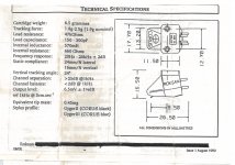
The phono cell I have is one that has been around for a long time but with relatively few hours of use is an MM roksan corus black mounted on a roksan trabiz-ZI / Roksan Radius I.
While reading the whole topic I had a doubt regarding the capacitance that is defined in the emerald and the ideal range of values for the corus black, if I am not wrong the emerald has 100pF of capacitance and the corus has the ideal range of 150-300 pF. Are there any capacitors that can be exchanged to approximate this range of values? Or is it nothing to worry about?
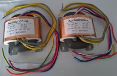
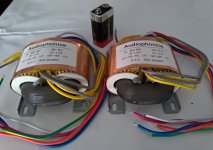
Here are the technical characteristics of corus black and what I already have for the construction of the emerald.
Best regards to everyone.
Carlos
I intend to build emerald (I have not yet ordered the plates from Richard) but I am already collecting material.
The phono cell I have is one that has been around for a long time but with relatively few hours of use is an MM roksan corus black mounted on a roksan trabiz-ZI / Roksan Radius I.
While reading the whole topic I had a doubt regarding the capacitance that is defined in the emerald and the ideal range of values for the corus black, if I am not wrong the emerald has 100pF of capacitance and the corus has the ideal range of 150-300 pF. Are there any capacitors that can be exchanged to approximate this range of values? Or is it nothing to worry about?
Here are the technical characteristics of corus black and what I already have for the construction of the emerald.
Best regards to everyone.
Carlos
Attachments
- Home
- Source & Line
- Analogue Source
- RJM Audio Emerald Phono Stage Help Desk