Hello,
I build tube amps for fun. I wonder about the origin of the components, I live in France. For electrochemicals there is F&T, but the ripple current and the lifespan are much lower than Pana ED model 47uF for exemple.
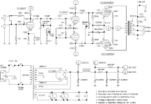
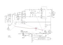
I am attaching a 5E3 type diagram to have a power supply in front of me.
What characteristics would be preferred please?
Tell me more !
Pana ED
https://fr.rs-online.com/web/p/condensateurs-electrolytiques-aluminium/4340380?gb=s
https://www.mersen.com/fr/produits/condensateurs
I build tube amps for fun. I wonder about the origin of the components, I live in France. For electrochemicals there is F&T, but the ripple current and the lifespan are much lower than Pana ED model 47uF for exemple.
I am attaching a 5E3 type diagram to have a power supply in front of me.
What characteristics would be preferred please?
Tell me more !
Pana ED
https://fr.rs-online.com/web/p/condensateurs-electrolytiques-aluminium/4340380?gb=s
https://www.mersen.com/fr/produits/condensateurs
Attachments
Last edited:
FT tan delta also much bigger than Pana's, so ESR is much bigger.
The 390R resistor limiting the first caps (47uF//47uF) charging pulses, so in case of Panasonic 47uF/450V the ripple current only 0.16A (simulated).
The 390R resistor limiting the first caps (47uF//47uF) charging pulses, so in case of Panasonic 47uF/450V the ripple current only 0.16A (simulated).
Thank you for responding. I still have questions in mind!
Have you simulated the power supply with PSUD?
Does ESR matter the same for C15 and C14?
The fact that there is a double RC improves the smoothing but could deteriorate the dynamics of the amp? I haven't seen an amp with 2RC in the PSU
!

Have you simulated the power supply with PSUD?
Does ESR matter the same for C15 and C14?
The fact that there is a double RC improves the smoothing but could deteriorate the dynamics of the amp? I haven't seen an amp with 2RC in the PSU
!

"Have you simulated the power supply with PSUD?"
No, I used LTSpice.
The C15 is the "last" capacitor for power stage, so low ESR is mandatory for dynamic behaviour.
BTW I would solve PSU differently.
For "large" current (power tubes, about 90mA sum) C-L-C.
Attention! At least 500V first capacitor needed.
Then smoothing R-C for EL84 g2. The voltage must be under (or equal) the static anode voltage.
Individual R-C for each VAS (12AY7, 12AT7) stages from C-L-C "output".
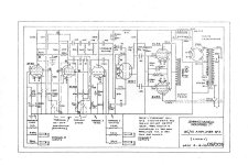
Ok, the choke must support 100-120mA. The PSU will be as the vox ac15_second schematic.
Initially, I used this "solution" (2RC) because the power transformer delivers 330 V and I had to drop the supply voltage. And because I'm a rookie !
Later I could modify the PSU.
Often power rails preamp are in series : better smoothing. You recommend a parallel assembly : like some Matchless amp., see schematic spitfire !
Why parallel instead of serie ?
Initially, I used this "solution" (2RC) because the power transformer delivers 330 V and I had to drop the supply voltage. And because I'm a rookie !
Later I could modify the PSU.
Individual R-C for each VAS (12AY7, 12AT7) stages from C-L-C "output".
Often power rails preamp are in series : better smoothing. You recommend a parallel assembly : like some Matchless amp., see schematic spitfire !
Why parallel instead of serie ?
Attachments
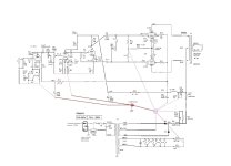
As can you see in original schematic, the first stage has individual PS filtering (5.3mA), the second+third also has.
The first stage current fluctuation is low, also similar the second stage. The third -phase splitter- usually consumes the greatest current, but in this case it's not so significant, so common filter (with second stage) is appropriate (7mA).
The sum of three input stages static current is 12.3mA, the EL84 second grids consumes in all 10mA (5+5mA).
The EL84 g2 currents fluctuates -even full-, so requires more precise filtering (relative to the anode).
Some implementation use simple pull-up resistors from g2 to B+, so grid voltage potential will be definite. I prefer this.
I suggest this:
C-L-C for power stage (despite the fact that PP has 28-30dB PSRR), g2 tided up to B+, via resistor; Presumed static current of power stage is 100mA.
R-C filtering for first stage (from CLC output); Presumed static current is 5.3mA.
R-C filtering to 2.-3. stage. Presumed static current is 7mA.
The whole current (112.3mA) flows through PSU choke, so at least 120mA capable requiring.
it could be better with this italian choke :
https://shop.piemme-elektra.it/Categories/89/Products/8973
I would still have to drop the voltage because 200 ohms for the choke againt 390 actually. I could put 150 ohm 14w resistors before the diodes otherwise the EL84s will suffer.
https://shop.piemme-elektra.it/Categories/89/Products/8973
I would still have to drop the voltage because 200 ohms for the choke againt 390 actually. I could put 150 ohm 14w resistors before the diodes otherwise the EL84s will suffer.
"very helpful because I use an 12AT7 and not an AX7, and others calculators here : https://tubes.astefo.com/fixed-bias-cathodyne-phase-inverter/"
Hello,
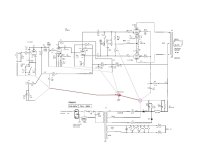
The modifications on the power supply, but also other things are finished : increase of the heating potential, tone cut, fixed bias cathodyne PI.
The diagram includes all the voltages.
The resistors R22 and 23 allow to have reasonable voltages for EL84.
The result differs from a pure 5E3 but I learned a lot thanks to this achievement.
And thanks again for the help!
Hello,
The modifications on the power supply, but also other things are finished : increase of the heating potential, tone cut, fixed bias cathodyne PI.
The diagram includes all the voltages.
The resistors R22 and 23 allow to have reasonable voltages for EL84.
The result differs from a pure 5E3 but I learned a lot thanks to this achievement.
And thanks again for the help!
Attachments
- Home
- Amplifiers
- Power Supplies
- Ripple current PSU caps vs other characteristics