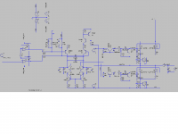
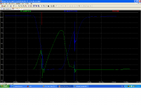
I am trying to choose initial values for my UcD from a LTSpice simulation, but I run into problems with ringings of the gate waveforms aswell as the associated rinings in switching voltage waveforms and current waveforms. I have attached two images below, and I hope to get some feedback regarding the trustworthyness of these LTSpice simulations. I have used Fairchilds "complete" model of FDP3682 which takes into account the body diode, wire inductance etc.
Attachments
Yes, they do look very bad (illegible really).
Perhaps you could try putting a small value resistor in series with each mosfet gate. This will prevent them from interacting as much, which may be part of the problem.
Perhaps you could try putting a small value resistor in series with each mosfet gate. This will prevent them from interacting as much, which may be part of the problem.
I already use gate resistors, the ringing occurs in spice no matter what value I give these, therefore I suspect that spice sucks.
The images look like **** from resizing, I have absolutely no clue of how ot resize with anti-aliasing in Windows as I am a complete newbie to microsoft products.
The images look like **** from resizing, I have absolutely no clue of how ot resize with anti-aliasing in Windows as I am a complete newbie to microsoft products.
zilog said:I already use gate resistors
Really? They don't even show up in the attached picture. I meant directly in series with each gate since you're using mosfets in parallel.
Are you using MS paint or something? Download the gimp. It's like photoshop but free. You can resize images nicely with that app. I'm not a 'native' windows user either but am forced to do so at work...
BWRX said:
Really? They don't even show up in the attached picture. I meant directly in series with each gate since you're using mosfets in parallel.
Are you using MS paint or something? Download the gimp. It's like photoshop but free. You can resize images nicely with that app. I'm not a 'native' windows user either but am forced to do so at work...
No need to go individual when parallelling a BSN254A and a FDP3682, orders of magnitude in difference between them. I guess the pictu´res are too bad to see the ringing if you dont know where to look.
The ringing is easily visible on your graph, I just can't read any of the text on the schematic.
Why do you have BS2N54A's in parallel with FDP3682's? If you disconnect the BS2N54A's is the ringing still there?
What is that dode and cap you have coming off the gates of the output fets?
Sometimes when you resize an image to a fraction of it's size that isn't 1/2, 1/4, 1/8, etc. the program can really mess it up.
BWRX said:The ringing is easily visible on your graph, I just can't read any of the text on the schematic.
Why do you have BS2N54A's in parallel with FDP3682's? If you disconnect the BS2N54A's is the ringing still there?
What is that dode and cap you have coming off the gates of the output fets?
Sometimes when you resize an image to a fraction of it's size that isn't 1/2, 1/4, 1/8, etc. the program can really mess it up.
I use the BSN254 to measure the output current by current sharing, so I include part of that circuit in the simulation to account for its drive requirements.
The ringing is still there independent of the BSN254.
with inductance + caps (even if only inside the mosfet) you make some nice resonating loops....so you always get some ringing.
this happens in real world also, so whats your problem??
btw: i think, spice (or swcad) always shows correct results, as long as the models u use are perfect. (and whats perfect in this world...)
this happens in real world also, so whats your problem??
btw: i think, spice (or swcad) always shows correct results, as long as the models u use are perfect. (and whats perfect in this world...)
- Status
- Not open for further replies.
- Home
- Amplifiers
- Class D
- ringing of mosfets in UcD simulation