I've seen two different arrangements for magnets in ribbon tweeters.
In the tall neodymium ribbon tweeter article on the internet. It is claimed to be a version of the Apogee tweeter. It has two magnets next to each other
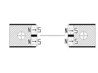
(front and back) ((both left and right)). The front/back magnets are separated with a rubber strip, and the tweeter ribbon is placed between the left and right rubber strips. See attachment.
I've also seen where there is one magnet on each side of the ribbon, and the ribbon is placed between these two magnets on the front edges.
The former setup uses thinner magnets, the latter uses thicker magnets,
I think the cost would be comparable.
Which would give the strongest magnetic field.
In the tall neodymium ribbon tweeter article on the internet. It is claimed to be a version of the Apogee tweeter. It has two magnets next to each other
(front and back) ((both left and right)). The front/back magnets are separated with a rubber strip, and the tweeter ribbon is placed between the left and right rubber strips. See attachment.
I've also seen where there is one magnet on each side of the ribbon, and the ribbon is placed between these two magnets on the front edges.
The former setup uses thinner magnets, the latter uses thicker magnets,
I think the cost would be comparable.
Which would give the strongest magnetic field.
Attachments
I've seen two different arrangements for magnets in ribbon tweeters.
In the tall neodymium ribbon tweeter article on the internet. It is claimed to be a version of the Apogee tweeter. It has two magnets next to each other
(front and back) ((both left and right)). The front/back magnets are separated with a rubber strip, and the tweeter ribbon is placed between the left and right rubber strips. See attachment.
I've also seen where there is one magnet on each side of the ribbon, and the ribbon is placed between these two magnets on the front edges.
The former setup uses thinner magnets, the latter uses thicker magnets,
I think the cost would be comparable.
Which would give the strongest magnetic field.
The idea behind the two magnet rows is to achive a more even magnetic field.
The apogee driver was the "diva" mid driver, not the tweeter.
The magnet-gap-magnet motor structure does provide a more uniform field over a longer front-back displacement than a single 2x height stack of the same number of magnets. This motor structure also provides some self centering between large displacement transients. Simulation show that this is a good design option with low flux ceramic magnets, or small NdFeB magnets. (pic1 and sim_pic2)
With larger high strength NdFeB magnets a steel "magnetic lens" (pic3) can be used to maintain a uniform flux over longer front-back displacements.
With even larger, wider, high strength NdFeB magnets the center gap field is uniform enough over a 0.1"-0.2" to not require additional more complicated engineering. I favor this simple construction.
figures here #15
http://www.diyaudio.com/forums/planars-exotics/198983-apogee-ribbon-questions-2.html#post2781901
I have not seen a tweeter ribbon which uses the magnet-gap-magnet motor, as it was developed for large Xmax displacement midrange ribbons.
A magnet attached to each steel pole is best for the low Xmax ribbon displacement on a tweeter. There are many clever details on how the ribbon is corrugated, the top/bottom attachment, top/bottom dampening options, and the bezel construction. The impedance step-up transformer is simple to build, but difficult to find the best ferrite cores.
There are several very good threads detailing design and construction.
"The tall neodymium ribbon". Part 1
This is the link of the ribbon tweeter I was looking at.
So, I guess usually ribbon tweeters are more like this:
Or for maximum field strength should the ribbon be at the front edge of the magnets.
Thanks,
Paul
This is the link of the ribbon tweeter I was looking at.
So, I guess usually ribbon tweeters are more like this:
Or for maximum field strength should the ribbon be at the front edge of the magnets.
Thanks,
Paul
"The tall neodymium ribbon". Part 1
This is the link of the ribbon tweeter I was looking at.
So, I guess usually ribbon tweeters are more like this:
Or for maximum field strength should the ribbon be at the front edge of the magnets.
Thanks,
Paul
I'm the author of that website and responsible for the driver so I do recognice it😉
Most other ribbons are not made as I have done this one. The two row system is not a project for
someone with a short temper, there will be some 😡


during building. I'm having bad days still, and I have built quite a few now.
A single row of magnets is a lot easier to build and as "Linesource"
pointed out good enough if you are going for a ribbon width that isn't as wide as mine are.
Ps. I'm gluing the magnets with epoxy in all drivers today, it's highly recomended.
Last edited:
- Status
- Not open for further replies.
- Home
- Loudspeakers
- Planars & Exotics
- ribbon tweeter magnet placement