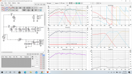
I had to stop for a few days to clear my head. I look better now, impedance is above 4ohms everywhere. Still not crossed over where it should be, not off by much but the woofer mid area is where my trouble is , I seemed to fixed a area and created a problem. Could be my xo design a elementary school hot mess. I’ll post a pic tonight for a good chuckle.

Some quick thoughts, or things I would fix:
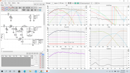
Your bass section is very lossy, with that big series resistance in there. Also why the highpass on the bass section?
Mid/high phase tracking is poor. Your high pass and low pass acoustic slopes are quite different. Your crossover points should sum flat at -6dB for each driver.
Your response is quite far from flat and the bass and treble shelving will be noticable in the final result.
One more thing, try to target component values you can actually purchase. You can lock in E6 or E12 values in VituixCAD.
Last edited:
The bass section is ported, reason for HP.
Juggling impedance is my issue. I can get a better result but the xo points are way off. Partly keeping the cap values reasonable size as well. I’ll put up a few other sets.
I didn’t realize it had a setting for available values
Juggling impedance is my issue. I can get a better result but the xo points are way off. Partly keeping the cap values reasonable size as well. I’ll put up a few other sets.
I didn’t realize it had a setting for available values
In theory what is more important in the sims, the FR or how the crossover slopes?
Attached is what I feel is a decent frequency response. The xo looks odd, the woofers seem to be higher in level that I cant pull down without throwing things out of whack . I had to series caps to get it to look like that.
Im just over 7db down at the mid/woofer xo but the woofer level is still up. I know the impedance is not doable, I'm still wrapping my head on how everything works together.
Whats generally preferable to raise impedance or is the design so far off I need to start over?
The series caps I used to pull down the peak and keep the caps for getting ridiculously sized.
Attachments
Your second woofer inductor is a short circuit problem, it needs to go.
Also, is it helping you to have the redundant components in the mid circuit or could you consolidate them for simplicity?
Also, is it helping you to have the redundant components in the mid circuit or could you consolidate them for simplicity?
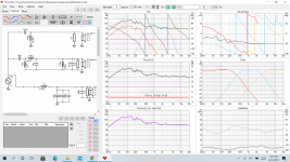
You are designing your notch filters wrong.
Series LCR in parallel with the driver for an out of band notch.
Parallel LCR in series with the driver for an in band notch.
Watch your impedance curve. Try not to dip below about 3R.
FR and good phase tracking are both important. I wouldn't want one without the other.
Series LCR in parallel with the driver for an out of band notch.
Parallel LCR in series with the driver for an in band notch.
Watch your impedance curve. Try not to dip below about 3R.
FR and good phase tracking are both important. I wouldn't want one without the other.
How would you describe your problem with the woofers?
The woofers appear about 7dB more sensitive than the mids and highs. Easy fix. Lose one of them, solves many problems.
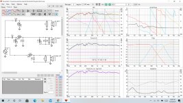
Can you let me know if this is a hot mess. I finally was able to get the 2 12's to combine and keep impedance above 4 ohms. My xo filters look whacked but the FR is good.
Certainly seems to be a exercise in futility at moments. It has made me question why not just go active, may save me some long drawn out heartaches.
I tried to keep the xo as simple as possible but the mid band proved formidable to me. Besides expense is it overdone or just plain wrong.
The setup is SRT-7, SB 6NeroMRN, 2x Faital 12pr320 16ohm
Why does the FR response show flat but the filter way down???
Attachments
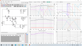
You have some crazy impractical component values in there. There is a 22 Henry inductor for a start and a 56mH and 120mH. Your mid drivers are 1M away from the tweeter and woofers. At 600Hz you have three seperate bandpasses all summing to +9dB. I'm not even sure where the extra bandpass came from. The system has no bass, being ~-3dB at 80Hz.
Are these even actual driver measurements taken in your test enclosure? It looks like you are using arbitrary measurements you have pulled off the web. If this is the case we are all just wasting our time trying to help you. The drivers will behave very differently in your final enclosure than they do in a half space environment or IEC baffle.
Are these even actual driver measurements taken in your test enclosure? It looks like you are using arbitrary measurements you have pulled off the web. If this is the case we are all just wasting our time trying to help you. The drivers will behave very differently in your final enclosure than they do in a half space environment or IEC baffle.
^the 22H inductor can just be replaced with a 100R resistor, since the inductance is so large that it doesn't affect anything in the audio range, only the DC resistance is having any effect on the crossover. A lot of the components on the mid are probably redundant. The filter response doesn't look like anything that can't be achieved with a more straightforward lowpass and highpass. If the huge component values are an attempt to flatten the impedance at Fs of your mid, I would go about this differently. Just implement the highpass and then tune the highpass filter to achieve the crossover frequency and Q that you need. You are probably going to either work with the Fs of the mid, which dictates putting the crossover highpass near to Fs, or move up your highpass sufficiently higher than Fs so that the effect of the resonance (a spike in the response of the mid) has negligible impact on the system response. You'll have to measure frequency response and impedance yourself in the final enclosure if your crossover is sensitive to the impedance at Fs. Deriving these from the datasheet won't be accurate enough.
for X Y and Z distances in VituixCad, x is horizontal alignment (all drivers x=0 if arranged in a vertical line, e.g. a slim floorstanding speaker). y is horizontal alignment so if the centre of the tweeter is 0.15m above the centre of the mid, and the centre of the woofer is 0.2m below the centre of the mid then y is +0.15m for the tweeter, 0m for the mid and -0.2m for the woofer. The further the listening position from the speaker, the less x and y matter. If your drivers are 1m apart then you probably won't get a consistent response unless you are listening from more than 5m away. I.e. it'll have a certain response at 2m, then it'll be different at 5m, then by 10, 15, 20m it'll basically sound the same as at 5m.
z is depth, should all be z=0 as the phase data in your measurements should account for this. If you derive the frequency response/phase data from datasheets it will all be wrong between different drivers so it's a complete gamble if you will get proper phase alignment unless you measure the real speakers yourself.
In a car you always sit in the same position so it is far more acceptable to have the drivers spaced far apart and require your head to be within a few cm optimal listening position for good sound. When I was into car audio I built a system which had every driver digitally time aligned and EQ'd to perfection... at least for me. Probably didn't sound nearly as good for people who weren't my height but I didn't care as I built that system for me and for me only. Also sounded like hot garbage in the passenger seat as all the delays/EQ were asymmetrical.
If you don't care about your home speakers requiring a 'head in a vice' listening position then go ahead and have huge CTC distance between your drivers, however, when you stand up or move one seat over, a huge hole may suddenly appear in your treble. Minimising CTC ensures that when you design for perfect on-axis response at a particular listening distance, you still get a reasonably nice response though a range of listening distances and off-axis angles.
for X Y and Z distances in VituixCad, x is horizontal alignment (all drivers x=0 if arranged in a vertical line, e.g. a slim floorstanding speaker). y is horizontal alignment so if the centre of the tweeter is 0.15m above the centre of the mid, and the centre of the woofer is 0.2m below the centre of the mid then y is +0.15m for the tweeter, 0m for the mid and -0.2m for the woofer. The further the listening position from the speaker, the less x and y matter. If your drivers are 1m apart then you probably won't get a consistent response unless you are listening from more than 5m away. I.e. it'll have a certain response at 2m, then it'll be different at 5m, then by 10, 15, 20m it'll basically sound the same as at 5m.
z is depth, should all be z=0 as the phase data in your measurements should account for this. If you derive the frequency response/phase data from datasheets it will all be wrong between different drivers so it's a complete gamble if you will get proper phase alignment unless you measure the real speakers yourself.
Worth noting that the whole purpose of minimising the centre-to-centre distance is to prevent combing/nulls in the off-axis response.In car with tweeters at ear level and midrange next to your feets works great, end results always depends on setup
In a car you always sit in the same position so it is far more acceptable to have the drivers spaced far apart and require your head to be within a few cm optimal listening position for good sound. When I was into car audio I built a system which had every driver digitally time aligned and EQ'd to perfection... at least for me. Probably didn't sound nearly as good for people who weren't my height but I didn't care as I built that system for me and for me only. Also sounded like hot garbage in the passenger seat as all the delays/EQ were asymmetrical.
If you don't care about your home speakers requiring a 'head in a vice' listening position then go ahead and have huge CTC distance between your drivers, however, when you stand up or move one seat over, a huge hole may suddenly appear in your treble. Minimising CTC ensures that when you design for perfect on-axis response at a particular listening distance, you still get a reasonably nice response though a range of listening distances and off-axis angles.
Last edited:

You have some crazy impractical component values in there. There is a 22 Henry inductor for a start and a 56mH and 120mH. Your mid drivers are 1M away from the tweeter and woofers. At 600Hz you have three seperate bandpasses all summing to +9dB. I'm not even sure where the extra bandpass came from. The system has no bass, being ~-3dB at 80Hz.
Are these even actual driver measurements taken in your test enclosure? It looks like you are using arbitrary measurements you have pulled off the web. If this is the case we are all just wasting our time trying to help you. The drivers will behave very differently in your final enclosure than they do in a half space environment or IEC baffle.
Certainly not trying to waste anyone’s time, your post is informative and some things I can’t get out of a book. You are correct I do not have the drivers in hand yet. I’m trying to get a handle on all this that I can’t get from a book. I built my IB 10 yrs ago partly because of your build so thanks for documenting 😎
Thank you @TMM, good info for me to digestion
- Home
- Loudspeakers
- Multi-Way
- Ribbon spacing with midrange