@Extreme_Boky
Good points.
The board's already been freshed up with new electolytic caps.
To update my "tweaks" in addition to the 470uFs (C8) and the 75 ohm R7's, I also replaced R6 (the factory 120 ohms) with 100 ohms.
The preamp now plays beautifully, very seductive, sounds "high end" to my ears.
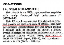
Shame that the IC is an old type and no info/replacement on it, but hell, I'm not messing with it!
Dead silent background.
The power supply I'm using is well-filtered, regulated, no problems.
Time to order a nice aluminum case for it from Mouser to use as a stand-alone phono preamp. 🙂
Good points.
The board's already been freshed up with new electolytic caps.
To update my "tweaks" in addition to the 470uFs (C8) and the 75 ohm R7's, I also replaced R6 (the factory 120 ohms) with 100 ohms.
The preamp now plays beautifully, very seductive, sounds "high end" to my ears.
Shame that the IC is an old type and no info/replacement on it, but hell, I'm not messing with it!
Dead silent background.
The power supply I'm using is well-filtered, regulated, no problems.
Time to order a nice aluminum case for it from Mouser to use as a stand-alone phono preamp. 🙂

LR7 to 75 ohms should do it.
M5214L Is pretty good as is HA 1457 from same period.
M5214L Is pretty good as is HA 1457 from same period.
I did some back-of-an-envelope calculations checking the correction network values (big envelope):
1. Theoretically, 56 kohm instead of 62 kohm for R5 should give a much more accurate first pole. There is no way a manufacturer of consumer equipment will use an E24 value when an E12 value works better, so I guess R5 is deliberately made a bit higher than the theoretical value to correct for finite op-amp gain.
2. The cancellation between the second zero and the pole of R8 and C10 actually gets better with wiseoldtech's modified values for R6 and R7 (100 ohm and 75 ohm).
Thanks for the interest and the additional research, Marcel.
The few relatively simple changes that I did, and using a well known couple of LP's on a known turntable (Dual 1009F/Stanton 500) clearly made a remarkable difference.
As the old saying goes: I know when something sounds right.
The slight boost was implimented to bring the preamp up closer to other line-level sources, because as we all know, many stock "phono inputs" tend to sound quieter than say, a tuner, tape, or CD volume level.
That last change (R6) of reducing the 120 ohm to 100 ohm brought the music and vocals into perfect balance, I was amazed.
Since the board uses a common power supply for both channels, they are seperate, independent, with two single op amps.
The "soundstage" is, to use an audiophile term, "breathtaking".
The d/s for M5214L is elusive, but a lot can be extracted from the serv. manuals
where the part in question were used:
Pioneer SX-3700, RT-909
Sony TA-F45_55
Luxman L-116A
Hitachi HA-3, -4800, HCA-4590
Yamaha A-450_550, C-6, R-2000
Mitsubishi -?
It looks like HV IC ~(+-)32V.
where the part in question were used:
Pioneer SX-3700, RT-909
Sony TA-F45_55
Luxman L-116A
Hitachi HA-3, -4800, HCA-4590
Yamaha A-450_550, C-6, R-2000
Mitsubishi -?
It looks like HV IC ~(+-)32V.
Attachments
Hello, I am piggybacking on this thread just to get the eyes of people already familiar with this schematic - I am repairing a Sansui 4900Z, and it uses this exact same phono amp board, except that my schematic shows 2.2uF for iC1, the input filter cap. However, my actual board in the stereo had the 10uF electrolytic cap in place, per Old Wise Tech's schematic.
I have a 2.2uF Panasonic film cap that I have installed in place of the 10uF electrolytic. My (limited) understanding is that this change will only the high pass cutoff by a few Hz - is there any other negative effects to using the 2.2uF cap at C1?
I have a 2.2uF Panasonic film cap that I have installed in place of the 10uF electrolytic. My (limited) understanding is that this change will only the high pass cutoff by a few Hz - is there any other negative effects to using the 2.2uF cap at C1?
It increases the effect of the noise current of the op-amp and the thermal noise of R2 somewhat - by a negligible amount if the designers made a sensible choice for the op-amp type. Then again, as that 2.2 uF is a film capacitor while the 10 uF was an electrolytic capacitor, it reduces the thermal noise of the effective series resistance of the capacitor.
Marcel, thank you very much. I'll leave the 2.2uF film cap in place, and then I will see about getting the 75 ohm resistor to sub for R7, based on your previous calculations.
- Home
- Source & Line
- Analogue Source
- RIAA preamp tweaking?