In simulation:Put a series resistor with a capacitance of 100-470µF in parallel with R4. The value of the resistor sets the new gain (in parallel with the old R4).
Original:
20Hz +56.48dB
100Hz +56.92dB
1kHz +56.96dB
10kHz +57.06dB
Modified
20Hz +61.19dB
100Hz +62.45dB
1kHz +62.82dB
10kHz +62.97dB

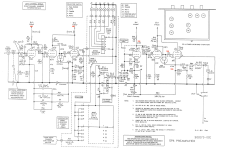
Please excuse my side question.. what is the purpose of C1 and C2? I've seen these in some active riaa schematics as in this thread.. and never (so far) in passive riaas..
hope you don't mind me chiming in @tonescout thanks
hope you don't mind me chiming in @tonescout thanks
My analysis is that R4 does very slightly affect the frequency response (I am assuming the open-loop gain is high enough to not feature significantly in the transfer function).
If we consider just the 'shelving gain' part of the response, i.e. remove C6, this leaves a pole-zero pair.
The LF gain will be (R9' + R10 + R4) / R4 (R9' = R9||R50).
The HF gain will be (R10 + R4) / R4
So the gain ratio is (R9' + R10 + R4) / (R10 + R4) = 1 + R9' / (R10 + R4)
As it is a pole-zero pair, this will also be the ratio of the pole and zero frequencies, which therefore does have a dependancy on R4.
However, as R4 << R10, the sensitivity to R4 is very low, and in the case shown, going from an R4 of 1.8k -> 1k will only give a delta of ~0.8%, which corresponds to a gain delta of ~0.07dB, or a shift of ~4Hz on the 500Hz breakpoint. So hardly likely to be noticable.
T4 is the 318uS time constant of the RIAA curve: the zero where it flattens out from ~500Hz up to 2122Hz.Sorry, for being dumb but what is T4?
C1 in the first section reduces the LF gain. With it eliminated all is copasetic. With it in circuit you obtain the results I listed. (Lipshitz mentions in section 7 of his paper)However, as R4 << R10, the sensitivity to R4 is very low, and in the case shown, going from an R4 of 1.8k -> 1k will only give a delta of ~0.8%, which corresponds to a gain delta of ~0.07dB, or a shift of ~4Hz on the 500Hz breakpoint. So hardly likely to be noticable.
C1 does not appear in the SP3 or SP6 phono sections from which I thought the OP schematic was lifted.
Reading the various values of the components, I expect not so much more open loop headroom for further increasing of the closed loop gain. FB correction is in the original design some 6x (very approx - can be wrong), so 4-5 dB gainlift leaves the FB with 3x, a very small margin. Close to component variation bandwidth (not freqs!), and thermal issues.It sounds a lot better now, more power and dynamics and actually a lot warmer and richer [The 3K was a 2W Allen Bradley] - is there any way of logically determining the limit of what is sensible within the valves operating boundaries?
So with my 'new' circuit I have this below.
The original R4 at 1.8K||3K= 1.1K effectively as 'new' R4
IMO with an input from the cartridge of 3.5mV there is no issue with the new bias point.
Can I assume the gain I am hearing is a combination of the bias point creating more gain AND the feedback being reduced?

The original R4 at 1.8K||3K= 1.1K effectively as 'new' R4
IMO with an input from the cartridge of 3.5mV there is no issue with the new bias point.
Can I assume the gain I am hearing is a combination of the bias point creating more gain AND the feedback being reduced?
Yes.
Closed loop gain = open loop gain * feedback, or better: Ao = Au * At
(At is the amount of open loop gain used for feedback).
Increasing the closed loop gain reduces the amount of feedback, and comes with increasing distortion.
Closed loop gain = open loop gain * feedback, or better: Ao = Au * At
(At is the amount of open loop gain used for feedback).
Increasing the closed loop gain reduces the amount of feedback, and comes with increasing distortion.
Open loop gain is ~67dB, raising the gain from 57dB to 63dB is going to limit overhead margin.
That affirms my thought (#30). So there's only 4dB (1.6x) left for correction.
If it sounds better to you, I guess you like the parabolic transfer (harmonic) of the tubes (no opinion, respected).
As noted by jackinnj, inside the loop the signal can reach this limits, especially the high frequencies compared with the feedback signal at the first stage (V1). This is not about absolute values (it's mV's), the high frequencies 10 times higher then the cartridge specifications (35mV), but small differences between the input signal at the grid and the feedback signal at the cathode are hardly corrected anymore, 'smoothed' somewhat better to say. A plain thought: you have pushed the pre amp just out of its well designed optimum, but to your liking though.
So to help me understand a little better if you have the time and inclination (I know we are all busy 😀 ) and I have no immediate need other than knowledge transfer. 
When I Iook at this calculator and play with the variables to get close to the two scenarios I get to this comparison as below.


Then I think ok, so let's add a 3.5mV signal to both and compare the headroom (saturation and cut-off) and clearly the 3.5mV swing is not troubling that, and the apparent spacing of the curves seems also to not become imbalanced. Then I move onto feedback changes from reducing the open loop gain and 'correcting' the distortion and then I get confused Many choose/prefer no feedback as a sound quality (it's often quoted as a selling feature) and others deem it necessary for controlling a circuit, and I know some circuits absolutely need it.
Then I look at the actual quoted gain of the Phono stage = 60dB - 26dB (for the line stage) = 34dB and then I see 63dB and my brain freezes!! 😵
When I Iook at this calculator and play with the variables to get close to the two scenarios I get to this comparison as below.
Then I think ok, so let's add a 3.5mV signal to both and compare the headroom (saturation and cut-off) and clearly the 3.5mV swing is not troubling that, and the apparent spacing of the curves seems also to not become imbalanced. Then I move onto feedback changes from reducing the open loop gain and 'correcting' the distortion and then I get confused Many choose/prefer no feedback as a sound quality (it's often quoted as a selling feature) and others deem it necessary for controlling a circuit, and I know some circuits absolutely need it.
Then I look at the actual quoted gain of the Phono stage = 60dB - 26dB (for the line stage) = 34dB and then I see 63dB and my brain freezes!! 😵
With a Phono preamp you should actually assume the maximum amplitude at the highest frequencies, so in this case 35mv. But in the statically calculated example, there is indeed nothing wrong.Then I think ok, so let's add a 3.5mV signal to both and compare the headroom (saturation and cut-off) and clearly the 3.5mV swing is not troubling that, and the apparent spacing of the curves seems also to not become imbalanced.
The open loop gain is larger with a smaller Rk (R4, from 1k8 to 1k1) in the first stage, but in this case the closed loop gain also increases. This two values are getting closer together and the result is less feedback.Then I move onto feedback changes from reducing the open loop gain and 'correcting' the distortion and then I get confused
Both the AC and DC settings change due to this chosen more closed loop gain. This does not necessarily lead to a better performance.
To find out how the two settings relate to each other, a detailed open loop analysis should be performed for both. In this case with 35mV input signal at 20kHz and without the riaa-network but instead it's representing impedance as a fixed value.
This topology depends completely upon feedback, for ac, dc and thermal stability.Many choose/prefer no feedback as a sound quality (it's often quoted as a selling feature) and others deem it necessary for controlling a circuit, and I know some circuits absolutely need it.
Open loop / feedback-less amplifiers (small signal, power) are a different kind of sport. And there is always some local feedback involved.
This is a bit cryptic remark, but do prevent a successive brain meltdown.Then I look at the actual quoted gain of the Phono stage = 60dB - 26dB (for the line stage) = 34dB and then I see 63dB and my brain freezes!!
The 'actual quoted gain of the phono stage = 60dB' is the same as jackinnj's "raising the gain from 57dB to 63dB".
Some people consider 57 to 60 dB or 60 to 63 dB as almost the same, but it differs a ratio of 1.4 for both.
Your "26dB (for the line stage)" refers indeed to the line stage but with the increased gain setting (R27 connected yields 25dB, without it is 15dB).
All these values are closed loop.
The open loop gain of the first (riaa) stage is 67dB (jackinnj), so its feedback margin is reduced to only 4dB, which is itchy small.
There is no reference of the line stage open loop gain... diagonally estimated at some 20x (26dB) for V4 and 25x (28dB) for V5, and is 500x (54dB) in total.
Concluding that the line stage in high gain mode still has 28dB feedback margin, which is abundant.
ahh well, it is worth noting that 60dB for the phono circuit is INCLUSIVE of the line stage 26dB so effectively it's 34dB
So open loop of 67dB to a now estimated 34+4 = 38 dB is a comfortable margin?
Thoughts!??
So open loop of 67dB to a now estimated 34+4 = 38 dB is a comfortable margin?
Thoughts!??
Calculations on a handwritten draft, log functions with the calculator on the apple.
Unmodified gain V1 = 21.7x (27dB), modified gain V1= 30.6x (30dB).
Gain V2 = 24.8x (28dB).
Open loop gain phono stage is Av1 * Av2 = 538x (55dB) unmodified, 759x (58dB) modified.
I did not take into account the grid bleeder as an extra load to the anode.
Also for that diagonal ease: µ = Sd * Ri; ECC83: 100 = 1.6mA/V * 63kΩ; rk = 1/Sd = 600Ω (Sd is the dynamic S, not the static!).
Summarizing:
RIAA phono amp open loop gain is 55dB unmodified, 58dB modified.
RIAA phono amp closed loop gain is unmodified:
@ 10kHz 14x (23dB)
@ 1.0kHz 73x (37dB)
@ 100Hz 307x (50dB)
RIAA phono amp closed loop gain is modified:
@ 10kHz 23x (27dB)
@ 1.0kHz 118x (41dB)
@ 100Hz 501x (54dB)
Gain increase with modfication is 4dB over the audiable spectrum.
Feedback margin is decreased with modification from 5dB to 4dB @100Hz (predicted in #36).
Flat line amp open loop is 500x (54dB).
Flat line amp closed loop is 5,7x (15dB) without R27; ditto 17.5x (25dB) with R27 (#36).
Feedback margin is 39dB vs 29dB; both abundant.
Scenarios (all @ 1kHz):
Unmodified RIAA, unmodified line; 3.5mV x 73 = 256mV, x 5.7 = 1.46V~ (pro audio level, consumer is 250mV, semi pro is 0,775V)
Unmodified RIAA, modified line; 3.5mV x 73 = 256mV, x 17.5 = 4.48V~
Modified RIAA, unmodified line; 3.5mV x 118 = 413mV, x 5.7 = 2.37V~
Modified RIAA, modified line; 3.5mV x 118 = 413mV, x 17.5 = 7.23V~ (good for a SIT class A source follower!)
Triodes are easy to calculate as long as one has to realise that RA//ra and Rk+rk for the actual gain per tube.
The phono amp is almost running on empty, the line amp has plenty milage.
What was the reason for the phono stage modification actually?
Thanks for the analysis, this is great learning.
The reason to change the gain in the phono, was to make the volume level a little more comparable to the gain on the line level with DAC output coming in. Specifically I also found the phono stage to sound a little flat and lacklustre, and my instinct was this was due to a lack of drive into the line stage by comparison.
When I changed the resistor, the sound improved IMO with more projection and energy and life in the music, and also to some extent more bass and lower midband.
As FYI and background for my line stage, I played around with feedback quite a bit by changing the feedback resistor as a single item (losing R27) to end up with a 3K6, which by comparative logic I think gives me abut 20-21dB of gain? So I thought I could play around with the feedback on the phono to get a balance I liked. 🙂
I have found in my system to my ears normal gain preamps (e.g. 12dB line stage) to not sound as real as this old preamp, somewhat annoyingly as I for a long period of time could not wait to justify the purchase of a shiny new preamp. I tried some pretty expensive and well regarded preamps and the Sp8 just musically trumped them.
That's when I joined DIYAudio and tried to fix a residual hum in the Sp8 that 2 repair guys (expensively) could not fix, BUT with your help on this forum it's silent now.
- Home
- Source & Line
- Analogue Source
- RIAA preamp feedback circuit gain