I'm trying to understand and implent this RIAA pre amp.

So, I decided to simulate it. Knowing a MM cartridge gives out about 5mV at 1Khz, what voltage level should I consider, during the simulation process, at 20Hz, 50Hz, 500Hz, 2.1KHz and 20Khz?
So, I decided to simulate it. Knowing a MM cartridge gives out about 5mV at 1Khz, what voltage level should I consider, during the simulation process, at 20Hz, 50Hz, 500Hz, 2.1KHz and 20Khz?
It's easiest to add an inverse RIAA circuit before the input, and then use a constant amplitude sine for the test signal. The midband gain is about 43dB, so for around 1V output, you need about 7.1mV input.
Tweak the input level for exactly 1V out at 1kHz and sim the frequency response.
An inverse RIAA network will have a HF zero above the audio band, instead of continuing to rise at +20dB/decade. Then the measured response will fall above the audio band, since this RIAA circuit
does have the proper -20dB/decade at HF, due to the 75uS supplied by the passive output RC.
Last edited:
IC riaa preamps are fine, however I prefer to lean more for "purity of tone" by using the time-tested two transistor style preamp.
The signal only has to pass through those two transistors, instead of the dozen or more inside an IC chip.
Much close to a "straight wire" with gain.
The signal only has to pass through those two transistors, instead of the dozen or more inside an IC chip.
Much close to a "straight wire" with gain.
That is Rod Elliot's P06 RIAA preamp from Hi-Fi RIAA Phono Preamp
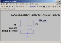
If you're using LT Spice you can use the 'e' component (voltage dependent voltage source) with a Laplace function in the value parameter as in the image below.
If you're using LT Spice you can use the 'e' component (voltage dependent voltage source) with a Laplace function in the value parameter as in the image below.
Attachments
I've built that circuit, it works, and it sounds great, at least to my ears.
If you want a PCB which fits in a small case and includes a voltage splitter (accepts single DC supply), let me know, you can have one for postage.
If you want a PCB which fits in a small case and includes a voltage splitter (accepts single DC supply), let me know, you can have one for postage.
R2L's only purpose seems to be to increase the noise. Similarly the impedances of the first RIAA network could be scaled down to reduce noise a bit.
The 100nF decoupling cap between rails is missing.
C1L/R3L's time constant looks a bit dodgy to me (caveat I haven't simulated this!)
The 100nF decoupling cap between rails is missing.
C1L/R3L's time constant looks a bit dodgy to me (caveat I haven't simulated this!)
IC riaa preamps are fine, however I prefer to lean more for "purity of tone" by using the time-tested two transistor style preamp.
.
You'll enjoy this if you haven't already seen it.
You'll enjoy this if you haven't already seen it.
I'm confused by that, could you elaborate?
Thank you guys, all the sugestions will be considered. The thing is, I need about 500mV on the output to for the next stage, which will be a phaser, yes, I'm going quadraphonic!
http://www.saturn-sound.com/images ... 4ch decoder - hi-fi news - dec 73 - pt 2.jpg
As shown on the image, the next stage requires 500mV, so, I run a simulation and obtained the following outputs at 1KHz:
3.5mV @ 1KHz --> 402.395mV
4mV @ 1KHz --> 459.879mV
4.35mV @ 1KHz --> 500.119mV
4.5mV @ 1KHz --> 517.302mV
5mV @ 1KHz --> 574.849mV
Having those results in mind, and considering a RIAA preamp has a difference of about 40dB between 20Hz and 20KHz, will this circuit do the job and give out the required voltage level on the audible band?
> which will be a phaser
Without looking at the actual phaser: I'm quite sure the "500mV" is nominal, basically your 5mV needle figure times 40dB typical preamp gain. Actual needles exceed 30mV@1kHz on LOUD parts (so 3V out of the preamp) and of course down to zero or vinyl hiss. I bet the phaser is all-the-same up to 4V or 8V input. This is not like fitting a swimsuit! More like a one-size-fits-most poncho.
Without looking at the actual phaser: I'm quite sure the "500mV" is nominal, basically your 5mV needle figure times 40dB typical preamp gain. Actual needles exceed 30mV@1kHz on LOUD parts (so 3V out of the preamp) and of course down to zero or vinyl hiss. I bet the phaser is all-the-same up to 4V or 8V input. This is not like fitting a swimsuit! More like a one-size-fits-most poncho.
..."purity of tone" by using the time-tested two transistor style preamp....
I've been working with 2-Q RIAAs for decades. It is pretty easy to show that this form does not have enough gain to be "real good".
Consider first: 47k input, Gv@1kHz=100(40dB), and assume a 47k load. Gain at <50hz is 10X from 1kHz so 1,000. Since Zin and Zload are the same, this requires a Current Gain of 1,000.
Because transistor parameters vary part-to-part and time and temperature, a NFB plan is highly favored. But this wants an additional gain of 10X to ensure "large" NFB. So Current Gain of 10,000.
Yes, we can pluck two transistors with hFE>100. However we need DC feed and base bias networks, and we want good DC stability. We use much of hFE in the infrastructure. An RIAA NFB plan of reasonable Z becomes a hard load in the treble (tho we typically have ample gain up there). Also the assumed 47k load is no longer standard, 22k and 10k inputs are getting common.
The 2-Q plans tend to be sloppy in the bass, with hFE=300. Even with hFE=900 they do not shine.
I have moved (since ~1977) to 3-Q plans. Usually implement the second stage as a Darlington so as to preserve your "purity of tone" by having Q2 Q3 work in the same direction. Macintosh had their own version(s), a nice plan was published in Audio Amateur.
Yes, plenty of output. Depending on your cart you can always reduce or increase the gain as detailed in the instructions.Thank you guys, all the sugestions will be considered. The thing is, I need about 500mV on the output to for the next stage, which will be a phaser, yes, I'm going quadraphonic!
http://www.saturn-sound.com/images ... 4ch decoder - hi-fi news - dec 73 - pt 2.jpg
As shown on the image, the next stage requires 500mV, so, I run a simulation and obtained the following outputs at 1KHz:
3.5mV @ 1KHz --> 402.395mV
4mV @ 1KHz --> 459.879mV
4.35mV @ 1KHz --> 500.119mV
4.5mV @ 1KHz --> 517.302mV
5mV @ 1KHz --> 574.849mV
Having those results in mind, and considering a RIAA preamp has a difference of about 40dB between 20Hz and 20KHz, will this circuit do the job and give out the required voltage level on the audible band?
I've been working with 2-Q RIAAs for decades. It is pretty easy to show that this form does not have enough gain to be "real good".
Consider first: 47k input, Gv@1kHz=100(40dB), and assume a 47k load. Gain at <50hz is 10X from 1kHz so 1,000. Since Zin and Zload are the same, this requires a Current Gain of 1,000.
Because transistor parameters vary part-to-part and time and temperature, a NFB plan is highly favored. But this wants an additional gain of 10X to ensure "large" NFB. So Current Gain of 10,000.
Yes, we can pluck two transistors with hFE>100. However we need DC feed and base bias networks, and we want good DC stability. We use much of hFE in the infrastructure. An RIAA NFB plan of reasonable Z becomes a hard load in the treble (tho we typically have ample gain up there). Also the assumed 47k load is no longer standard, 22k and 10k inputs are getting common.
The 2-Q plans tend to be sloppy in the bass, with hFE=300. Even with hFE=900 they do not shine.
I have moved (since ~1977) to 3-Q plans. Usually implement the second stage as a Darlington so as to preserve your "purity of tone" by having Q2 Q3 work in the same direction. Macintosh had their own version(s), a nice plan was published in Audio Amateur.
Interesting about your Darlington arangement.
I assume that increases the output dramatically?
Most 2Q preamps do sound quieter as compared to say, the FM or Aux selector, and of course this is partly due to low cartridge output (2-2.5 mv).
I've lowered the Q1 emitter resistor to about half the original value (560 to 270 ohms) in order to boost output of Q2 with good results.
Amplification overall @ 1 kHz = 115.
500mV / 115 requires 4+ mV... @ 1kHz
That's a typical MM/MD output before RIAA, so all signs green.
500mV / 115 requires 4+ mV... @ 1kHz
That's a typical MM/MD output before RIAA, so all signs green.
http://www.saturn-sound.com/images ...4ch decoder - hi-fi news - dec 73 - cct 1.jpg> which will be a phaser
Without looking at the actual phaser:
http://www.saturn-sound.com/images ...4ch decoder - hi-fi news - dec 73 - cct 2.jpg
Thank you, if you care to see, there you go. But, this was just a reference, I'm actually gonna implement this other circuit.
http://1.bp.blogspot.com/-a99d5AHTZ...48/HwhhiOkFIx8/s1600/ETI-sq-decoder-lores.jpg
I just thought of the 500mV as a reference, as showm on the comments of the circuit.
> which will be a phaser
Without looking at the actual phaser: I'm quite sure the "500mV" is nominal, basically your 5mV needle figure times 40dB typical preamp gain. Actual needles exceed 30mV@1kHz on LOUD parts (so 3V out of the preamp) and of course down to zero or vinyl hiss. I bet the phaser is all-the-same up to 4V or 8V input. This is not like fitting a swimsuit! More like a one-size-fits-most poncho.
I would like to promote these two PRR-quotes as basic DIY-rules by default:
PRR quantumrule ONE:
This is not like fitting a swimsuit!
PRR quantumrule TWO:
More like a one-size-fits-most (q?) poncho.
These rules apply to all DIY... experiments.
Circuit's? Serious important issue alongside Lipschitz tbt!I have moved (since ~1977) to 3-Q plans. Usually implement the second stage as a Darlington so as to preserve your "purity of tone" by having Q2 Q3 work in the same direction. Macintosh had their own version(s), a nice plan was published in Audio Amateur.
That is Rod Elliot's P06 RIAA preamp from Hi-Fi RIAA Phono Preamp
If you're using LT Spice you can use the 'e' component (voltage dependent voltage source) with a Laplace function in the value parameter as in the image below.
So, by using this source, I should expect a flat responce over the audible band? And, is this the same as playing the 7th and n8th track of this record?
The Ultimate Analogue Test LP - Δίσκος βινυλίου για Δοκιμές
- Status
- Not open for further replies.
- Home
- Source & Line
- Analogue Source
- RIAA phono pre amp.