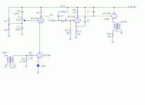
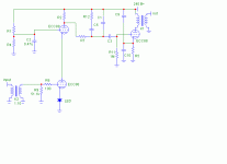
Or run the input tube at a decent current
That's the ticket!
Thanks,
Point taken, (and not that I wouldn't try it) but is that a big enough change so that it's really a different design? Steve has a number of designs that he runs at lower than usual currents. I built an 801 amp he described. Have to say, it sounds really nice.
Sheldon
Point taken, (and not that I wouldn't try it) but is that a big enough change so that it's really a different design? Steve has a number of designs that he runs at lower than usual currents. I built an 801 amp he described. Have to say, it sounds really nice.
Sheldon
Brian Beck said:Another crazy idea I will probably regret posting:
Since R2 is already referenced to a presumably noisy B+ (the lower end sees a high resistance in the cascode which doesn’t ground it away), reference the signal voltages to B+, not to ground. Don’t fight B+ noise, join it!
Connect the bottom ends of C5 and C1 not to ground, but to B+. Bypass R5, not to ground, but to B+ also. Now the second stage will amplify only the difference voltage between grid and cathode, which are both referenced to B+, and B+ noise is largely ignored as common-mode. You’ll still end up with a ground-referenced output, so some noise re-injection/cancellation might be necessary, perhaps at the upper cascode grid, but the results might still have lower noise. Or, did anyone say OPT?
No regrets yet? Maybe this will push it over the edge: I haven't recalculated various resistor/cap values, but this is where you were headed (with a nod to SY here too)?
Attachments
Almost! First of all, remember, I was just musing about the B+ referencing - I haven't tried it or seen others do it exactly like this for an RIAA stage, but I think it will work (I see this kind of thing in the solid-sate world). Just don’t go creating PC boards quite yet. If you’re adventurous, try it and let us know.
For the OPT, I was thinking of using the primary instead of the 22K plate load, R3. Then get rid of the last ECC88 stage altogether. C1 doesn’t look right in any case, so it should go. Done this way, now all the AC voltages are referenced to the B+, noisy or not, except for the cartridge and the secondary, but that’s OK. To the extent that the first cascode has even a tiny bit of power supply rejection, this will actually work against our new scheme, but the rejection is R2/(R2+95K) or better at higher frequencies, the latter term being roughly the impedance looking down into the upper cascode’s plate. So you may need to re-inject some AC-coupled noise back in somewhere. Try it and see first, though. I didn’t check your gains and overload margins, so I’ll leave that to you.
No regrets yet so long as you are game to try this out given my disclaimer...
Thanks Brian,
I'll probably give a try to a variation on the original, as I have the tubes and an appropriate power transformer already. And the basic working values have been tested - no small issue for a newcomer to all this. All I'd be doing is adding some optional bells and whistles. Also, with significantly higher current for the cascode in this latest schematic, I'd be on the edge of current capacity of my iron. So you are probably safe.
Still, your suggestions are very useful as a mental exercize for me to better understand the general issues. Testing that assumption: C1 in that last schematic was for the 75us roll off, and I can't just toss it. But I could incorporate its function into a one pass type of network between the cascode and output tube. I think I agree that the noise injected by C8 and R19 should probably go, at least mostly. On the other hand, it could be for fine tuning - adding no noise or just a touch. Interestingly, with doing this sort of stuff, one would want to have a fairly noisy supply to make it easy to dial in the cancellation. Then set the supply on quiet mode for operation (That's something I don't see discussed often - how to make a supply switchable between noisy and quiet). Your design has the nice attribute of fewer parts (which is tempting), but maybe trickier to tune as some caps are sort of dual function? Gains I think I can calculate. More reading before I'm ok with overload margins, but I'll mess with it. .
If I do try this alternate approach (B+ bypassing) to noise cancellation on this project, don't worry you won't be held accountable, unless it works really well.
Thanks again,
Sheldon
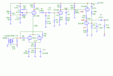
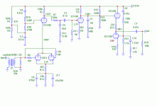
Well, I built this thing and it works. Ok, only one channel so far, and I haven't checked for RIAA accuracy, or fiddled with the cartridge load resistor. But it sounds fine on first blush and is quiet. I think can reduce the very slight hum even a bit further with some ground tuning. I turns on smoothly with no thumps or screeches. I do get a turn off thump and wobble in the low bass, along with some mid range buzz at power off. Can always shut it down after the amps, if I can't figure out an easy way to calm that down. Circuit:
Attachments
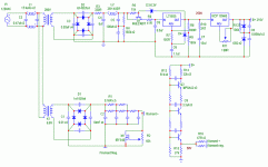
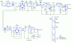
And power supply. Belt, suspenders, and clips. The CLC part is ordinary. What look like Zeners at the output are actually OB2 gas tube regulators (no symbol in Microcap). So it's shunt regulators fed by a current source. The HV regulator in front of the current source is there to provide some protection in case a shunt tube fails. It limits the voltage to 250V. I can actually try both ways too - series or shunt, as I have less than 200uV after the series reg. alone. I took MJ's design, but had to increase the base resistor to 15K to get it to regulate at lower currents (I found that here somewhere). Even still it needs 10 or so mA to regulate. I guess a Darlington would be the call if regulation at lower current is desireable.
That weird little shunt on the filament supply is for the same reason. If I pull out all the tubes, I get 7.5V. Without it I get 10.5V. I can also adjust the trimmer to set the voltage on the filaments. It doesn't reduce the ripple, which is around 25mV.
The Thingy (from Morgan Jones) lifts the filaments about 50V.
edit: One thing not shown on the schematic (ran out of gas making the schematic), is filtering on the filament supply. It has capacitors and a common mode choke after the transformer, and and a CMC on the output. I'll try and add these and post the final.
Attachments
Sheldon said:I think can reduce the very slight hum even a bit further with some ground tuning.
The ground is a star arrangement, with the signal separate and connected only at the star point. This all seems fine, as minor changes make no difference at all. The big difference is in shielding. Hum went from 4 or 5mV to less than one mV when the first two tubes are shielded and the rest is shielded with a metal case. Next test, RIAA accuracy.
Sheldon
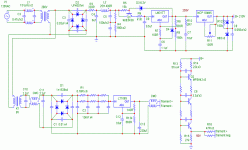
Sheldon said:corrected/complete ps:
Oops, not quite. Some errors in the filament supply. Also made some changes. Some intentional, some because I was not careful with a probe and "bang" out came the magic smoke.
In the error category, the input filter to the filament supply is now correct, including the CMC on the output.
Intended change is the regulator on the filament supply. Found that my original transformer was not quite up to the task, so I took a 12V transformer I had and rewound the secondary to give about 8V with some load. Then added the reg., adjusted to about 6.1Volts.
The LT1085 and the transistor for the Miada style regulator on the HV side was a victim of an errant probe. Took me a while and a few more destroyed bits to finally sort it out. This schematic reflects what I had left to do the job with. I'm keeping my probes out of there now.
Sheldon
Attachments
Built the other channel and got it checked out. Everything runs fine and it sounds good. Very quiet, can hear a trace of hum, ear next to speaker at full volume, almost none at normal listening levels. What is there is 60Hz and varies depending on where I position the preamp section. So it suggests some small inductive pickup. If it were more, I'd do some more shielding, but it's not enough to fool with.
I'm running the power supply at 53mA. The preamp takes about 20mA per channel, leaving 13mA for the OB2's. Here's the final. I replaced the pot on the front end noise cancelling circuit with a divider, after finding the null point with injected noise. The only thing left off the schematic are the stopper resistors on each of the grids.
I'm running the power supply at 53mA. The preamp takes about 20mA per channel, leaving 13mA for the OB2's. Here's the final. I replaced the pot on the front end noise cancelling circuit with a divider, after finding the null point with injected noise. The only thing left off the schematic are the stopper resistors on each of the grids.
Attachments
Next up is to try some low current LED's for biasing the first tube. The dynamic impedence of the little green ones looks pretty good no?: http://www.vishay.com/docs/83030/83030.pdf
Sheldon
Sheldon
The first stage has me curious. Why do you have the current set so low? The 6072 curves suggest that it will be more linear at 2-2.5mA per section. That will also run the ECC88 at a more linear point and, if you choose (wisely, I think) to use LED bias, the LED will also be happier.
BTW, you can pick up slightly more gain by moving C3/R11 to the input tube side of the RIAA network.
BTW, you can pick up slightly more gain by moving C3/R11 to the input tube side of the RIAA network.
SY said:The first stage has me curious. Why do you have the current set so low? The 6072 curves suggest that it will be more linear at 2-2.5mA per section. That will also run the ECC88 at a more linear point and, if you choose (wisely, I think) to use LED bias, the LED will also be happier.
BTW, you can pick up slightly more gain by moving C3/R11 to the input tube side of the RIAA network.
Thanks for the comments Sy.
The first two tubes are basically a design by Steve Bench. As pretty much a rank beginner, I went with his approach, at least to start. He seems to successfully run a variety of tubes outside what would be considered their normal range. Complimentary effects? Looking at his site, he does a lot of distortion testing. He doesn't specifically show numbers on this project, but it's more likely to have been checked than many other designs in the DIY universe. Now that it's done, I can play some with the operating points. Only bad part is that my compulsion to make things compact, makes it more difficult to change stuff. I'll post some pics in a week or so.
Actually, Steve had cap C3 and the grid leak resistor on the other side, as you mention. In moving it, I was following MJ's suggestion - makes it easier to compute the RIAA network. So why not just follow the design here too? Consistency, who me? Well here, and in adding the noise cancellation on the front and back end, and the Aikido type follower , I wanted to stretch a bit and see if I could pull it off, and to see if I could properly figure the RIAA comp. values. Same applies to the weird power supply. My own private lab, as it were. Wanted to try a bunch of stuff I hadn't done before. It all does work, so I'm pleased with that. And I learn a lot from the discussions, your last post included.
I built an inverse RIAA network to check the final result. I found a little signal generator on the net and stepped from 10Hz to 20kHz, while measuring the output amplitude. Everything was close and only out by about a dB at the either extreme.
Sheldon
SY said:The first stage has me curious. Why do you have the current set so low? The 6072 curves suggest that it will be more linear at 2-2.5mA per section.
It doesn't change the qualitative issues, but I realized that the voltage drop over the cathode resistors is actually a little higher than shown. As operating now, I get about 0.7mv for the cascode. It wouldn't be too hard, even with my cramped layout, to change the load resistor (R2) and cathode resistors (or led). I would need to recompute the first RIAA section, but would probably only need to change R13- so doable for sure. May give this a shot after I've had a chance to listen to it for a while.
Sheldon
- Status
- This old topic is closed. If you want to reopen this topic, contact a moderator using the "Report Post" button.
- Home
- Amplifiers
- Tubes / Valves
- RIAA Phono Amp Design
