I HAVE A HAMMOND TOROIDAL TRANSFORMER 44V CENTER TAP 160VA, 4 CAP 4700UF NICHICON FW DECOUPLING 0.01 POLYESTER METAL BY CHANNEL. PHILIPS AND 2 REGULATORS 7824 VISHAY ONE FOR EACH CHANNEL. THANK YOU!
Maxpou,
Please turn off the Caps-lock. I'm sure it's not your intention but this style is considered as shouting.
As for the PSU, a schematic would be handy as well.
/Hugo 🙂
Please turn off the Caps-lock. I'm sure it's not your intention but this style is considered as shouting.
As for the PSU, a schematic would be handy as well.
/Hugo 🙂
7824 regulator might be too noisy, just a hunch. How much decoupling do you have after the regulators?
This circuit has a low first stage gain followed by the RIAA network attenation so it won't be that quiet. As Peranders has said, it is also very sensitive to supply noise.
Hi,
Try batteries with as much bypass capacitance you can afford.
Apart from PSU, this is a forgiving circuit: it was my first project a while ago since 15 years or so and it worked quiet good.
Rüdiger
Try batteries with as much bypass capacitance you can afford.
Apart from PSU, this is a forgiving circuit: it was my first project a while ago since 15 years or so and it worked quiet good.
Rüdiger
you can use this "cleanup" circuit from Wenzel Associates -- the entire article can be found on their website. Just make sure that the opamp you use can take the voltage. (i.e. you don't want to use one of those low power, low voltage ones.)
Paralleling more 2sk170's on the front end will reduce "device" noise further (at the expense of more current consumption).
http://www.wenzel.com/documents/finesse.html
Paralleling more 2sk170's on the front end will reduce "device" noise further (at the expense of more current consumption).
http://www.wenzel.com/documents/finesse.html
An externally hosted image should be here but it was not working when we last tested it.
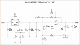
i made some research and i found this schematic for my PS. what do you think this schematic? thank you!!🙄
Hi maxpou,
how much noise do you have with your existing approach? With an humble LM317 Regulator and with MM-Cart it should at least be listenable. If noise (what kind of noise?) overrides the signal then something else is probably wrong, be it grounding, wiring of the cart or whatelse.
how much noise do you have with your existing approach? With an humble LM317 Regulator and with MM-Cart it should at least be listenable. If noise (what kind of noise?) overrides the signal then something else is probably wrong, be it grounding, wiring of the cart or whatelse.
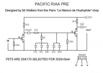
If you are using a MM cartridge, you shouldn't have much of an inherent noise problem with this preamp unless there is something wrong with layout, grounding, or power supply. I found the basic implementation of the Pacifiic to have too much overall gain for my system - I need about 40dB @ 1 kHz. I fixed the problem by using a 2SK170BL with source degeneration in the second stage. This also helped to center the second stage drain voltage to maximize output swing.
RIAA accuracy may also be suspect with this circuit. The passive RIAA filter is driven by an output impedance consisting of the Drain resistor in parallel with the output impedance of the first JFET. The values of the first resistor in the filter network may need to be changed to reflect this.
In my implementation of this circuit, I got around the problem by adding a source follower to each stage. The first one provides a low impedance to drive the RIAA filter - the second provides a low impedance to interface with the cold, cruel world outside... Check my thread "Open Loop Follies" if you want more details.
In my simulations of this preamp type, the first stage has low distortion due to the relatively low output signal. The second stage, however, will have 0.2-0.5% THD, almost overwhelmingly 2nd harmonic. I'm working off and on on an approach to cut the second stage distortion by a considerable amount, yet still remain open loop. I'll post when I have it up and running. I'm currently running a JFET SRPP preamp in my home setup, which has its own problems with RIAA accuracy due to variable gain vs. output load - see my JFET SRPP thread for more details (use search). The heavily modified Pacific preamp will replace the SRPP when it is ready...
Hi wrenchone,
I read your threads a while ago, lots of experimenting and thought, I like them.
The high distortion of the pacific may lead the listener to the conclusion, it performs with lots of 'drive' or 'pace'. Later, with more complex music, it becomes evident: just distortion...
But it's fun to play with it.
I like your idea to serve the passive riaa with some drive-current.
You did try cascoding the second stage, I guess? I wonder what would happen if you replace the source degeneration with a current source... (would it be possible/worthwhile without a negative supply? Hm, maybe I should put that circuit on the bench again...)
Rüdiger
From simulation, cascoding the second stage didn't seem to offer any big advantage, and high order distortion went up, if I remember correctly. In the first stage, cascoding does lower the parasitic capacitance presented to the cartridge. This is significant if you're dealing with a cartridge with 500mH-1H of inductance, like the Shures, Stantons, etc. I'm using a Grado Gold, so the stray capacitance is less of a problem (cartridge inductance of around 50mH). I added input cascode JFETs in my first Pacific mod preamp anyway (I already had places for them in the layout) but I didn't notice any huge difference in the sound. However, the modified Pacific was loads better than the stock Nikko preamp it replaced from the start - I noticed the difference instantly.
Using a current source in the second stage of the Pacific preamp would do you no good unless you bypassed it. That's getting to be too many parts (not to mention any effects from the capacitor), and you need a resistor in series with the bypass cap to get your degeneration back. Otherwise, your gain is too high again. Changing the 2nd FET to a BL with simple resistive degeneration just happened to strike the proper balance between gain and drain voltage centering.
Using a current source in the second stage of the Pacific preamp would do you no good unless you bypassed it. That's getting to be too many parts (not to mention any effects from the capacitor), and you need a resistor in series with the bypass cap to get your degeneration back. Otherwise, your gain is too high again. Changing the 2nd FET to a BL with simple resistive degeneration just happened to strike the proper balance between gain and drain voltage centering.
Noise isn't caused by VR, but by quite wrong conception of this configuration... 😉 Yes, is mighty simply, but it is all... 😉
Upapa, please be more precise. I built one of these preamps (albeit heavily modified) and found it to be quiet. Noise can be caused by power supply/VR if you make one of several mistakes:
1) If you put your preamp too close to a poorly designed power transformer (too much flux density in core, lots of fringing flux), you can get hum pickup.
2) Ditto if you put the preamp too close to the leads from the transformer to the rectifiers to the filter caps, especially if these connections have a large loop area. As an added bonus, you can pick up HF diode "snap" noise from the rectifiers. Even supposedly normal recovery rectifiers generate a lot of noise when used in a capacitor input filter. The noise spectrum reaches all the way down into the audio band, and up to a few hundred kHz. I see it all the time when doing EMI measurements on power supplies at work. The noise signature is quite distinct from the usual racket generated by a switcher. It looks like a continuum rising with decreasing frequency, with the switcher fundamental and harmonic peaks riding on top. The loop from XFMR to rectifiers to caps should be as tight as possible (twist feed and return leads together, etc.). Rectifiers (no matter what the purported speed) should be snubbed. I followed all the above nostrums, but took the extra step of locating my power supply in its own box, and use a cable to connect to the preamp.
3) Too much ripple on the power rails could feed through, especially if the regulator drops out in the ripple trough.
4) Is your regulator oscillating? Even three terminal IC regulators can oscillate quite nicely if not bypassed properly.
Other problems:
4) Sloppy layout could result in oscillation or ground loop (s).
5) RF puickup can also sause spurious noise, though the bandwidth on this preamp should be smaller than most.
6) Did you properly ground the TT to the preamp? Lotsa hum if you don't.
- Status
- Not open for further replies.
- Home
- Source & Line
- Analogue Source
- Riaa Pacific Jfet