Hey everyone.
I recently designed my first PCB.
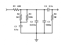
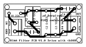
It's an RIAA filter circuit. The boards are 25mmx50mm (~1x2 inch). They are mono because I design my amps symmetrically.
As a special offer to fellow diyAudio members, I'm offering a pair of empty boards for 5$ USD shipped anywhere I can send mail to.
I will also offer the same as a kit with 5% tolerance parts rated for tube or SS duty to anyone here for an additional 5$ for a total of 10$.
For another 5$, I will assemble and test the boards for you.
The blank is being offered for those who want to use exotic parts.
Due to the spacing of the board, I recommend you use nylon screws or at least nylon washers.
If you get a kit, you will need 33nf - P=15mm, 2x 0.1uF - P=7.5mm, 1000pf - P=15mm. Any resistors up to 1/2W will fit these boards. The connectors are standard 2 pin 5mm spaced blue screw terminals, or you can solder directly to the board...
If you're interested, send a PM 🙂
The parts I include are suitable for anything that has a Zout of 600R or less, but the topology is the topology. You can change the values to suit your individual filter design goals.
Cheers!
Koda
I recently designed my first PCB.
It's an RIAA filter circuit. The boards are 25mmx50mm (~1x2 inch). They are mono because I design my amps symmetrically.
As a special offer to fellow diyAudio members, I'm offering a pair of empty boards for 5$ USD shipped anywhere I can send mail to.
I will also offer the same as a kit with 5% tolerance parts rated for tube or SS duty to anyone here for an additional 5$ for a total of 10$.
For another 5$, I will assemble and test the boards for you.
The blank is being offered for those who want to use exotic parts.
Due to the spacing of the board, I recommend you use nylon screws or at least nylon washers.
If you get a kit, you will need 33nf - P=15mm, 2x 0.1uF - P=7.5mm, 1000pf - P=15mm. Any resistors up to 1/2W will fit these boards. The connectors are standard 2 pin 5mm spaced blue screw terminals, or you can solder directly to the board...
If you're interested, send a PM 🙂
The parts I include are suitable for anything that has a Zout of 600R or less, but the topology is the topology. You can change the values to suit your individual filter design goals.
Cheers!
Koda
Attachments

Last edited: