Also, spoke a little too soon. There is still a buzz that immediately goes away with switching the mains off. So I have some work either in the power supply or heater wiring or grounding left.
Also I do not understand yet why grounding the driver grid completely gets rid of the noise also.
Also I do not understand yet why grounding the driver grid completely gets rid of the noise also.
Last edited:
Hopefully you have created all local ground loops (not long ground loops).
The idea is to contain all the current in the local loops first.
A local ground loop for the RCA jack return and input tube cathode return.
A local ground loop for the B+.
A local ground loop for the output tube grid and output tube cathode circuits.
A local ground loop for the IEC power socket (Ground lead to chassis). This is the only loop that connects direct to the chassis.
And that point also defines where the local ground loops tie to . . . the chassis.
I usually tie the IEC ground to the chassis on a ground lug, that is right at the IEC socket.
Only after you have created all of the first 3 local ground loops above, should you connect anything from them to the chassis.
I use one more ground lug to the chassis, and tie all the first 3 local ground loops to that 2nd ground lug.
Of course, I have to pay attention to wire placement; twisted wires for all AC power leads, and output transformer primary, etc.
TY. Maybe I am being too anal as the amp sounds really good and it is dead quiet when it is hooked up to a source.
The only thing I didnt do on your list is have a separate ground loop for the output tubes and driver. I am running the driver ground and PT cathode ground to the same point which is at the end of my ground bus.
The only thing I didnt do on your list is have a separate ground loop for the output tubes and driver. I am running the driver ground and PT cathode ground to the same point which is at the end of my ground bus.
Your buzz just could be getting into the grid from the heater windings. Sometimes the HT rectifier currents couple from the HT winding to the LT winding if you share the transformer. The capacitive coupling to the grid gives a buzz rather than a hum.
Since it goes away (mostly) when the grid is grounded I suspect the oscillation is causing grid current in the driver tube for that half the cycle. Which can explain the grid resistor effect. I think.
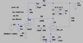
You might have grid current in 12at7, the sim shows it's about 120mV when the input is opened and 1Meg grid resistor. This grid voltage disappeared when the RCA connector is plugged in, and grid voltage gone down to zero. The grid resistor has little effect as there is still source output Z that is lower than 1Meg. The grid current flows through this RCA interconnect. It is better to use a blocking cap in the input to prevent grid current in the cable and allow grid resistor be accurately adjusted. The blocking cap has much effect on reducing phase shift towards zero and hence stability (oscillation etc) will be improved. For sim try to use Adrian's model as it's has grid current modeled.
Now help me tweak it
After gaining confidence that the amp will not destroy my "good" speakers I hooked it up and gave a listen. Very nice. Not quite up to the standard of my RM9 benchmark but very musical and I could live with it if I had to, happily.
Now I would like to improve it. So what would I play with? Add gnfb? play with upgrading the passive components? Or is it as good as its going to get without changing the topology? The schematic is shown below:
Attachments
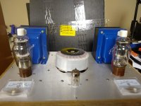
Nothing yet. Can I be happier? 🙂
But seriously just started listening and its pain to go back and forth with the RM9 (but I will at some point). My sense is the RM9 has a little more "air" in the soundstage. Vocals seemed just a bit more coherent with the RM9 versus slightly "smeared" with the RH807. However the enjoyment of the music is equal.
But seriously just started listening and its pain to go back and forth with the RM9 (but I will at some point). My sense is the RM9 has a little more "air" in the soundstage. Vocals seemed just a bit more coherent with the RM9 versus slightly "smeared" with the RH807. However the enjoyment of the music is equal.
Umm that's difficult to translate into LTspice. If its GFB you wish than you may need more gain to start with. Maybe a 12ax7 for first stage with less plate current, then gfb to cathode. can you share your .asc or maybe prefer to dabble yourself.
I can add a little to see what the effect is on sound. I have good drive with my preamp so I may not need that much extra gain. Is 3db NF enough to bother with as an experiment?
 Think this is how I would go. Adjust C3 for min ringing on 1KHz square wave. Sorry R1 should be 33k.
Last edited:


Thank you so much for noodling this for me.
I see you removed the Schade plate to plate feedback. Is this best practice to have one or the other? What would happen if you had both Schade feedback and a little gNFB? ( I guess I could just simulate that for myself but I was looking for a qualitative answer).
I see you removed the Schade plate to plate feedback. Is this best practice to have one or the other? What would happen if you had both Schade feedback and a little gNFB? ( I guess I could just simulate that for myself but I was looking for a qualitative answer).
I don't have an answer for that. The sfb is better for stability as its on the primary but does not include your first valve. I think for a small amp the gnfb will give lowest distortion. Experiment. Others will give you better advise.
For your amp seems the gnfb is better if you can get it stable. To do this on ltspice you need an accurate model of the transformer (linear will do).
For your amp seems the gnfb is better if you can get it stable. To do this on ltspice you need an accurate model of the transformer (linear will do).
Last edited:
- Home
- Amplifiers
- Tubes / Valves
- RH807SE HiPot test