Both the 12AT7 and 1625/807 are RF tubes. They are good for over a hundred MHz.
Depending on the wiring dress, wire lengths, and ground loops, you may have an oscillator.
Sometimes RF oscillations occur, and are squeging at an audio rate (blocking at a rate that is in the audio band).
That is like bursts of RF that are at a burst rate that allows you to hear it.
You might try a resistor with a wire wound around it, connected to the 1625 right at the plate cap connector.
If I take a picture of my wiring and annotate it, would that be helpful? would you be kind enough to comment on it?
From all the pictures of the bottoms of the amps that I see on the Tubes / Valves forum,
I doubt I will spot something from another picture posted there.
It is hard enough for me with my aging two eyes seeing in 3D, when a friend brings over a non working amp, that I can see in real 3D life.
The last time I did that, even with a schematic, it was a bit of a nightmare.
Of course, the person had modified the wiring somewhat, and that added to the difficulty of what was wrong. It was a stereo amp with a dual triode input phase splitter, a dual triode gain stage, and push pull 2A3 outputs.
After it was fixed, it was a very good amplifier again.
It is time to:
Draw and post accurate schematics for the amp, and for the power supply.
Change the 12AT7 input resistor from 1 meg to 50K.
Check the wiring for an input ground loop (RCA input return should be connected to the bottom of the input tube cathode self bias resistor. Then the bottom of the self bias resistor connects from there to the central ground point. Do not connect from the RCA return directly to the amp ground (and, it also must have insulating washers on the RCA input jack).
You said that the B+ CT was connected to the first cap ground. No, connect to the first cap negative, that is not ground. Make local loops, before you ever connect something to the central ground point.
Connect the CT direct to the first cap negative terminal; connect the first cap negative terminal to the second cap negative terminal; then connect from the second cap negative terminal to the amp central ground point.
Last edited:
Fair enough. I'll put a scope on this weekend and see what its doing.
In the meantime, its sounding really nice on my small bookshelf test speakers.
In the meantime, its sounding really nice on my small bookshelf test speakers.
.........I never found 1Meg on LTSpice had to use 1000k........
Literal "1Meg" should work in any SPICE.
"1M" often does NOT work as expected. SPICE reads that as 'milli'. You may think upper/lower-case makes a difference, but core SPICE goes back to days when computers might not have both upper and lower case, so the convention is to ignore case.
Attachments
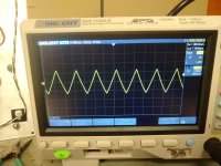
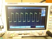
Did some scope measurements today. Squarewaves and triangles at 1 khz.
FFT showed 2nd harmonic down about 35dbv. Don't know if these numbers and pictures are ok/expected. Sounds good anyways. Comments?
FFT showed 2nd harmonic down about 35dbv. Don't know if these numbers and pictures are ok/expected. Sounds good anyways. Comments?
Attachments
It is time to:
Draw and post accurate schematics for the amp, and for the power supply.
Will do.
Change the 12AT7 input resistor from 1 meg to 50K.
Check the wiring for an input ground loop (RCA input return should be connected to the bottom of the input tube cathode self bias resistor. Then the bottom of the self bias resistor connects from there to the central ground point. Do not connect from the RCA return directly to the amp ground (and, it also must have insulating washers on the RCA input jack).
There isn't any input wiring yet. There is nothing on the driver grid other than the input resistor to ground.
You said that the B+ CT was connected to the first cap ground. No, connect to the first cap negative, that is not ground. Make local loops, before you ever connect something to the central ground point. Connect the CT direct to the first cap negative terminal; connect the first cap negative terminal to the second cap negative terminal; then connect from the second cap negative terminal to the amp central ground point.
The is exactly how I did it. I think... I have a 12bare copper ground bus which runs from the CT where the first cap is located to the 2nd filter cap to the dc ground central point. I have the earth (mains) ground connected to the chassis at the CT point.
Last edited:
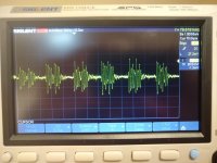
I replaced the resistor at the input with a 54K. Buzz level is down but still there.
Here is scope shot of what the noise looks like. Doesn't look exactly random does it?
Here is scope shot of what the noise looks like. Doesn't look exactly random does it?
Attachments
Last edited:
PS all linear.
Scope trace has nothing connected to the input. Just a 54k resistor from grid to ground.
Load is a 2-way speaker with 1st order xover.
Scope trace has nothing connected to the input. Just a 54k resistor from grid to ground.
Load is a 2-way speaker with 1st order xover.
Last edited:
Since it goes away (mostly) when the grid is grounded I suspect the oscillation is causing grid current in the driver tube for that half the cycle. Which can explain the grid resistor effect. I think.
Just looked at driver waveforms, grid voltage is random, cathode voltage is random. So it seems to be not happening there.
Using your scope to measure Cathode voltage signal/interference?
Is the cathode using a self bias resistor and a bypass cap across it, to ground.
You may be measuring a ground loop of some sort.
Your scope has a switching power supply, right?
Connect the scope probe ground clip to the amplifier chassis ground.
Connect the scope probe signal tip to the same point on the amplifier chassis ground?
(yes, I am having you measure, with the probe ground clip and probe signal tip shorted together, and both
connected to the chassis ground).
Do you measure an interference/noisy signal now?
If so, you have a "power mains - scope - scope probe - amplifier - power mains" ground loop.
A ground wire is a resistor, no matter how low of Ohms it is.
A ground wire is an inductor, no matter how low of uH or nH it is.
Current through a wire can create a ground loop (a voltage from one point on the wire to another point on the wire).
Scopes pass EMI requirements. They have to pass both conducted and radiated emissions lower than the standard.
But that does not mean that no current is conducted from the scope power cord, in common mode, in differential mode, or both.
That can induce a voltage into the probe, when the device being measured is also on the power mains.
Grounds are Commonly Misunderstood
So are wires.
Last edited:
6A3sUMMER you are a genius (relative to me...)
Scope chassis test passed. However the noise signal at the output transformer was the same with the amplifier off.
Did some other measurements but I will cut to the end. I discovered I had the OT secondaries floating. Once I grounded one end the secondary to the chassis with a clip lead the noise went away. Make sense?
Edit: I also noticed when I shut off the mains the noise instantaneously went away.
Last edited:
Always be sure to ground one connection of the secondary windings.
For all those amplifiers that do not use either any form of Global negative Feedback from the secondary, nor any form of cathode negative feedback from the secondary, all the other secondary configurations need to ground the Common terminal.
But in any case, for the secondaries that are used for negative feedback, one of the taps must be grounded.
So, in all cases, there needs to be a ground to one of the secondary connections.
A floating secondary capacitively couples signal from the primary. If the floating secondary wires come close to the output tube's grid wiring, or if the floating secondary wires come close to the input tube's grid wiring, you can create an oscillator.
Some oscillators run continuously, other oscillators run in bursts, on, off, on, off . . .
Last edited:
- Home
- Amplifiers
- Tubes / Valves
- RH807SE HiPot test