Thanks to all that have helped me on this journey but I have completed one channel of the RH807 (with 1625 tubes).
Powered up the driver section and compared to the spice model and that is OK.
First attempt with a power tube I heard an audible whine when the tube started to conduct at about 45ma and it continued to run away and I powered off. Replace the tube with another sample and it was fine running at a dc point agreeing with the spice model.
The Edcor 6.5K secondary was run open. Once I put a load of 10K on the secondary the singing stopped.
So before I dust of my scope and see what else may be happening is there any advice from this group? Is the open loop oscillation an indicator of a greater gremlin?
I have a grid stop but no plate stop resistor BTW.
The Edcor 6.5K secondary was run open. Once I put a load of 10K on the secondary the singing stopped.
Do not run an OPT without a load.
no load will create very high voltages across the output transformer primary. That can cause arcing inside the output tubes and, of course insulation breakdown in the transformer. Usually tube arcing does not cause permanent damage to the tube, but it is possible.
Question 1:
6.5k Secondary.
Don't you mean 6.5k Primary?
Don't shunt load the Primary.
Instead, always put a load on the Secondary.
If you load the secondary, and you still have to shunt load the primary to make the amp stable, you need to adjust the negative feedback circuitry; Or you have negative feedback in the wrong phase (which is positive feedback).
Global Negative feedback from the secondary, and to a lesser degree Schade negative feedback are particularly sensitive to poorly loaded transformer secondaries, especially when the output tubes are operated as either a Pentode, or as a Beam Power tube.
Triodes, Triode wired Pentode, and Triode wired Beam Power output tubes are generally easier to adjust the negative feedback for stability, unless the amplifier is designed with unneeded excess open loop gain.
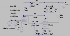
Please post a schematic. That may help to troubleshoot if you still have a problem.
6.5k Secondary.
Don't you mean 6.5k Primary?
Don't shunt load the Primary.
Instead, always put a load on the Secondary.
If you load the secondary, and you still have to shunt load the primary to make the amp stable, you need to adjust the negative feedback circuitry; Or you have negative feedback in the wrong phase (which is positive feedback).
Global Negative feedback from the secondary, and to a lesser degree Schade negative feedback are particularly sensitive to poorly loaded transformer secondaries, especially when the output tubes are operated as either a Pentode, or as a Beam Power tube.
Triodes, Triode wired Pentode, and Triode wired Beam Power output tubes are generally easier to adjust the negative feedback for stability, unless the amplifier is designed with unneeded excess open loop gain.
Please post a schematic. That may help to troubleshoot if you still have a problem.
Last edited:
You are confusing me.
A 6.5k Primary
and
An 8 Ohm Secondary is proper for a normal RH807 amplifier with 1625 tubes . . .
Not the other way round.
Again, please post an accurate schematic of your exact circuit, that you are basing on the RH807.
A 6.5k Primary
and
An 8 Ohm Secondary is proper for a normal RH807 amplifier with 1625 tubes . . .
Not the other way round.
Again, please post an accurate schematic of your exact circuit, that you are basing on the RH807.
I think 1m is actually .001ohm on your schematic I never found 1Meg on LTSpice had to use 1000k. I would also earth the 8R on the output for simulation and in real life. Try removing the 8R on simulation you may find it oscillates.
You are confusing me.
A 6.5k Primary
and
An 8 Ohm Secondary is proper for a normal RH807 amplifier with 1625 tubes . . .
Sorry I have xformer dyslexia. I corrected my post quickly but not before you probably got the response email.
When there is no load on the primary, L1 is a resonant circuit.
And above the resonant frequency, it is capacitive; below resonance it is inductive.
The 100k feedback resistor is driving the 33k resistor, and the very high 12AT7 plate resistance, rp. rp is high partly because of the already high natural rp of the 12AT7, but also because of the un-bypassed 12AT7 cathode resistor (and the RH circuit wants a high resistance there to make the circuit work well).
Phase shift is caused by L1 (it is inductive at low frequencies, resonant at mid frequencies, and capacitive at high frequencies).
A Beam Power tube (also a Pentode tube), has extremely high gain, it is due to Transconductance and Load impedance. With no load on the secondary, there is high impedance at the primary.
A circuit that has negative feedback, but still has enough gain at frequency extremes, and has 180 degrees phase shift due to the L1 reactances, and the phase shift of 100k driving plate capacitance, wiring capacitance, gives phase shift too.
You will have Positive feedback at some frequency.
That is what you had, Positive feedback (and that makes an oscillator).
Some simulation programs do not have enough information about the output transformer for the problem to show up.
When you put a load resistor on the secondary, that helps to 'swamp out' the resonance, and those reactances, it effectively puts a resistance in parallel with the primary. But there is also leakage inductance from the primary to the secondary. That also affects the loading at very high frequencies, even if the load resistor is on the secondary.
Your schematic says 6L6, your post #1 says 1625.
I hope you used the same values for all other parts as on the schematic, as a start for the first build.
One more thing, it is nice that your amp is working now.
Putting a loudspeaker load on is different than putting a resistor load on. Loudspeakers have reactances too, inductance, capacitance, resonance.
I notice you do not have any grid stopper on the 12AT7. The 12At7 was designed to be an RF tube for up to hundreds of MHZ.
What ever signal source you use may have reactances too, and certainly the shielded RCA cable is capacitive.
It would be a good idea to put a 1k resistor directly on the socket connection of the 12AT7, and apply the signal to the other end of that 1k.
Happy listening!
Last edited:
I used a 6LC in the spice model because I had a model for that. I assumed it would be close enough to the 1625 for DC op point purposes.
Thank you for the suggestion on the 12AT7 grid stop resistor.
Thank you for the suggestion on the 12AT7 grid stop resistor.
Wired the 2nd channel and it seems happy. The RH807SE design calls for a 330v B+ but alas I am only getting about 300v from my supply.
I assume that this is not a big deal for testing and maybe optimizing? Later I can get a transformer with more output.
I assume that this is not a big deal for testing and maybe optimizing? Later I can get a transformer with more output.
Can you post a schematic of your power supply?
The amp probably does not loose too much performance at 300V instead of 330V.
How much cathode current are you getting?
Cathode Volts / self bias resistance (of 400 Ohms?) = current in Amps.
The amp probably does not loose too much performance at 300V instead of 330V.
How much cathode current are you getting?
Cathode Volts / self bias resistance (of 400 Ohms?) = current in Amps.
Dont have it in digital form yet but:
250-0-250 PT
Full wave solid state rectifier
47uf input Cap
7H (240DCR) choke to separate channel B+
100uf per B+ rail
It measures a little less than PSUD predicts but pretty close.
Cathode current on power tubes about 55-60ma.
250-0-250 PT
Full wave solid state rectifier
47uf input Cap
7H (240DCR) choke to separate channel B+
100uf per B+ rail
It measures a little less than PSUD predicts but pretty close.
Cathode current on power tubes about 55-60ma.
Something is wrong.
250VAC x 1.414 = 353.5V peak.
With a solid state rectifier, and a 47uF input cap, you ought to get close to 350V at the cap.
The choke will drop according to the current draw x DCR
240 Ohms x 60mA = 14.4V.
And, even though you use 2 chokes, the total DC load current is more like 120mA.
Perhaps you did not model the DCR of the 120V and 250V windings.
Because the filter is cap input, the peak current draw is much more than the DC load current (more voltage loss due to the current peaks).
For a 120V primary to 250V half secondary, the primary DCR is probably less, but the current is about 2X that of the secondary.
Those two factors likely where you are getting some unexpected voltage drops.
Last edited:
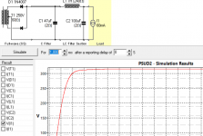
The no load voltage (no tubes) is 340V. (could my mains are at 110V not 120V I will measure).
PSUD predicts 350V no load. So 340V is reasonable.
With 60ma load PSUD sims 315v or 35v drop. So its in the ballpark with the sim. Snip of my sim screen and circuit attached.
PSUD predicts 350V no load. So 340V is reasonable.
With 60ma load PSUD sims 315v or 35v drop. So its in the ballpark with the sim. Snip of my sim screen and circuit attached.
Attachments
Last night actually hooked up a speaker to the output for a listensee. With the input grounded it was reasonably quiet. Holding my ear to the drivers I could hear a little buzz but I am happy. Input open was a buzzy hummy hot mess.
There is only a 1megohm grid resistor to ground so is this expected?
Next played some music through somewhat crappy speakers and it sounded good. I am happy as this is my very first tube power amp build.
Next step is waiting for parts so I can complete my input wiring instead of using clip leads to the input grids from by phone as a line source.
Check you have returned the transformer CT directly to C1 so the rectifier currents stay within this loop.
Yep, that is good. CT to C1 ground.
At lunch I put 1000R grid stoppers on the 12AT7. Hum buzz now turned into loud high pitch squeal. As long input is grounded or connected to a source its quiet.
Sounds good when it is playing. Clean highs and excellent sharp imaging. However still playing to crappy speakers, I hear midrange grunge but that could be the speakers. I do want to hook them up to my good speakers until put a scope on the output and do some sweeps.
- Home
- Amplifiers
- Tubes / Valves
- RH807SE HiPot test