AK posted his latest amplifier based on the 300B on his blog. I don't want this thread to turn into yet another "us against them" bash-a-thon 😉, so please limit your comments to the specific question below:
How do you get 12W with just 1% distortion using a single 300B?
Here is the schematic and simulation results from AK:

My simulation result was far from AK's,but pretty typical for a SE 300B amplifier - at 5W, the THD is ~4.5%, perhaps my tube models are messed up or quite different from the ones used by AK?
I'm on the road now, but I will try some other models when I get home, in the meantime, perhaps some of you sim-jockeys could run some sims to verify the results or better yet if anyone has actually built one already, please post the test results here.
TIA,
Jaz
How do you get 12W with just 1% distortion using a single 300B?
Here is the schematic and simulation results from AK:
My simulation result was far from AK's,but pretty typical for a SE 300B amplifier - at 5W, the THD is ~4.5%, perhaps my tube models are messed up or quite different from the ones used by AK?
I'm on the road now, but I will try some other models when I get home, in the meantime, perhaps some of you sim-jockeys could run some sims to verify the results or better yet if anyone has actually built one already, please post the test results here.
TIA,
Jaz
*yawn*
Another average design proclaimed a wonder.
AK says: "The simulation clearly shows 12W output at 1% distortion, with almost 2V RMS input sensitivity. I do not have any equipment that I could use to provide measurements, so DIY-ers will have to believe my word – or the simulation presented."
Really? he doesn't own an oscilloscope or a RMS voltmeter to measure the real output power of its amp? And a PC with Rightmark to measure distortion? 🙂
Vincent: You can't measure distortion with an oscilloscope. You can, however, measure it with a relatively inexpensive external sound card and some software. A dedicated distortion from yesteryear can be had for not that much money as well.
A simulation is only as good as the models that went into it. I generally find that simulations provide an excellent prediction of DC performance and "pretty good" prediction of AC performance. However, for distortion, I find the models to often be overly optimistic.
In my Damn Good 300B Amp, I simulated well over 10 W at 1 % THD and, I think, about 15 W at 3 % THD. Measured performance was 1 % THD at 9~10 W and 3 % THD at 11 W.
~Tom
... And a PC with Rightmark to measure distortion? 🙂
That's what I said.
Most 300B SE amplifier (with commercial 300B tubes) at 10W near to clipping.
Over 6-6.5W (depending of amplifier structure) starting A2 mode, increasing the distortion.
My 300B (D3a+CCS, "powerdrive", EH300B) over 10W begin to produce more odd harmonics due to clipping.
Over 6-6.5W (depending of amplifier structure) starting A2 mode, increasing the distortion.
My 300B (D3a+CCS, "powerdrive", EH300B) over 10W begin to produce more odd harmonics due to clipping.
Attachments

With 2.8 Vp at the input and 1.45V ECC81 bias, it is impossible to get 1% THD. Even in the bad simulations.
Most 300B SE amplifier (with commercial 300B tubes) at 10W near to clipping.
Over 6-6.5W (depending of amplifier structure) starting A2 mode, increasing the distortion.
Mine does nearly 10 W in class A1. You don't need to resort to A2 to get power out of the 300B. You just have to raise the B+ and anode current beyond the commonly used 360 V, 60 mA operating point. I find 400 V, 85 mA, 5 kΩ load to be just about right. That's still well below the max anode dissipation.
The biggest challenge of driving a 300B is that the driver needs to be able to drive the input capacitance of the 300B and deliver a 200 Vpp swing, cleanly.
~Tom
Rajkom: "With 2.8 Vp at the input and 1.45V ECC81 bias, it is impossible to get 1% THD. Even in the bad simulations."
I think that is just how his sim package shows the input level - Vp-p=2.88V, so Vp=1.44V. Unless he is clipping the input on purpose to generate high distortion, for distortion cancellation.
Tom's measurement results could be found here. Very nice!
Here is another example of a "typical" 300B amp THD characteristic (hope I'm not making too much of a generalization...)
Sofia Electric 91-01 300B, into 8 Ohm resistive load:
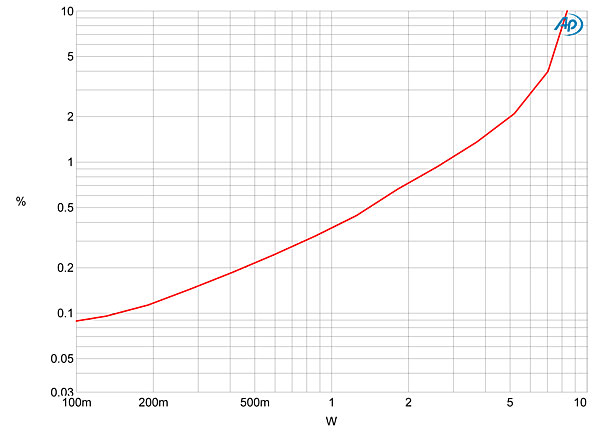
Tried a few things, but still no where near 12W @ 1% THD...
I think that is just how his sim package shows the input level - Vp-p=2.88V, so Vp=1.44V. Unless he is clipping the input on purpose to generate high distortion, for distortion cancellation.
Tom's measurement results could be found here. Very nice!
Here is another example of a "typical" 300B amp THD characteristic (hope I'm not making too much of a generalization...)
Sofia Electric 91-01 300B, into 8 Ohm resistive load:
Tried a few things, but still no where near 12W @ 1% THD...
Last edited:
Notice that the RH ECC81/12AT7 is still badly loaded down by the shunt Fdbk (as usuall for RH...) so the driver is making large amounts of 2H distortion for cancellation with the output 300B (probably close to nulling 2H at the max power rating) to get the low overall distortion figure.
At lower output power, the 300B 2H dist. comes down, but the driver 2H remains high, so the distortion figure will then go up with less power output. Unless the ECC81 2H dist. drops at the same rate, then it might continue to cancel out with the 300B. Would need to use the same tube models as Mr K used, and plot the dist. versus power level.
The EEC81 internal model parameters are very sensitive for getting the 2H dist. null at full power, so not just any sim model will work.
Last edited:
Most 300B SE amplifier (with commercial 300B tubes) at 10W near to clipping.
Over 6-6.5W (depending of amplifier structure) starting A2 mode, increasing the distortion.
My 300B (D3a+CCS, "powerdrive", EH300B) over 10W begin to produce more odd harmonics due to clipping.
What's the output level at 1.4% THD in your test?
What's the output level at 1.4% THD in your test?
10W (1kHz, 400V B+, 5k:8 transformer).
In my amplifier it happens.Thanks, so once the output gets past 10W, the THD shoots up due to clipping?
Other structure, other tubes (for example more powerful 300B tubes), other behavior...
After fixing my silly mistakes, I am getting more reasonable results from the simulations, below is a comparison of the THD of the RH300B with and without the plate-to-plate feedback.
At "high power" the distortion is much lower with feedback, however, at "low to mid power", strangely the THD is consistently higher than the amp without feedback. I'm also surprised by the low THD of 1.4% at 11.5W output (with feedback), since the waveform looks heavily clipped already...
Brown: without feedback, blue: with feedback
An externally hosted image should be here but it was not working when we last tested it.
I've gotten numbers close to that in the past by playing the harmonic cancellation game. Select the correct driver tube that pre-distorts the signal so the net result with the output tube's distortion measures low. The primary issue that I noted using this method is it leads to larger amounts of high order harmonics. That coupled with the fact that the audible loudness difference between 8W and 12W is barely perceivable, I moved onto other things. I’m not much of a 300B fan.
Yes, harmonic cancellation is definitely at work here. I know the above results are just simulations which may or may not reflect what the actual amplifier does, but I am somewhat at loss as to why the distortion is higher with the feedback, all except for the highest output. In your past experiment, did you observe the same behavior?
Those THD figures from your simulation look VERY optimistic. For sure they are without feedback.
If the aim is to build an easy 300B amp there is no need to make life that complicated. For a more serious 300B amp that circuit has too many flaws, IMHO. Feedback is unnecessary with 300B.
An easy 300B amp is: voltage amp with the two sections of an ECC83 in parallel, RC coupled to a cathode biased 300B. With the 300B at 400-420V/75 mA and 4K primary load one just needs to play with the ECC83 anode resistor in order to achieve useful 2nd harmonic cancellation which will be the only one at low power and the dominant up to the onset of clipping. It is possible to achieve low distiortion anyway: less than 0.2% at 1W and less than 2% at 10W as shown in the picturs below. This is a real amp as just described....
Attachments


Last edited:
Thanks for posting the screen shots. I was merely trying to verify RH300B's posted results as 12W with only 1% distortion seemed a bit optimistic - really no intention to build the amp.
Yes, harmonic cancellation is definitely at work here. I know the above results are just simulations which may or may not reflect what the actual amplifier does, but I am somewhat at loss as to why the distortion is higher with the feedback, all except for the highest output. In your past experiment, did you observe the same behavior?
It was a simple IT coupled two stage amp. (6AM4 - IT - 300B) It did not do as well when negative feedback was tried and the higher order harmonics got even more complex. The distortion started off low and then rose to around 2% at around 5W, it then dipped and stayed low until 9W where it climbed to 10% at 12W. It all had to do with the driver/output tube interaction. Like I said, its just a game you can play. I wasn't really all that impressed.
- Home
- Amplifiers
- Tubes / Valves
- RH300B 12W with 1% THD