Driving along the other night and all of a sudden the sub cut out. Get home and check out the amp, still had power and turned on (my heart sank at this point). Unhooked the sub and probed the speaker terminals playing a quiet test tone, left channel was fine and right channel was not. I immediately shut it down and disconnected the battery and fuse, then removed the amp from the car. I popped it open and measured the resistance across the various large transistors to play a game of "spot the difference" and the IRF540 on the right channel (Q215) was the loser. Been learning as much as I can about amp repair over the past day to be sure, final nail in the coffin was DMM diode check across terminals 2 and 3 was 0.2V which was less than half of the others'.
This amp was given to me by my father so I really want to fix it due to the sentimental value it has. I think I've got at least some idea of what I'll be doing but I figured I should double-check with the pros first to make sure I'm not overlooking anything else.
Couple things I've learned so far about replacing this transistor: Avoid the IRF540N as a replacement, stick to the regular IRF540; It's soldered to the MESHA board, seems the recommended way of handling it is using a torch.
My main concern is that I might be overlooking something else that the output transistor killed. Visibly everything is fine, but considering shipping on the replacement transistor costs more than the transistor itself I'm waiting on ordering it in case I should order other stuff to go with it. I'm not in a big rush, I'd rather make sure I don't screw this up.
I second what Perry said. That's my amp he is alluding to. Read the thread. Avoid any mistakes I made. Don't get in a hurry to reinstall the amp and try it without checking out the operation of everything you possibly can.
Concerning parts, it's smart to wait and order. Word of advice, order extra of everything while you are at it. You don't want to end up in the boat I'm in.
Concerning parts, it's smart to wait and order. Word of advice, order extra of everything while you are at it. You don't want to end up in the boat I'm in.
PC-3080-E, just like the schematic. However, I kind of got the feeling that this amp has been serviced previously, and the schematic has added to that suspicion.What's the PC # on the board in your amp?
Some of the transistors aren't lined up on the MESHA boards very well. Those transistors don't have the leads trimmed at all, and some of them had balls of solder at their base. The plastic around the power cable terminals is slightly melted too (was like that when I got it, not my doing).
Things that caught my eye as well:
- Q6 and Q7 are both labeled "MT P7 5N05HD", rather than the schematic's IRFZ40. (these also don't have their leads clipped)
- U1 is a TL494C, not TL594. The solder joints look excellent here though and the two are very similar so I'm guessing this was just a cost-cutting substitution.
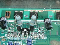
- R136, R236, R163, and R263 are strange. They have the color code Black-Orange-Silver-Gold on the same blue-colored body as R251 in this photo, rather than the black-colored bodies of the resistors on the bottom of that picture. (That pic looks notably similar to this amp too 😛) What purpose do those resistors serve? They're right in front of the output transistors so I'm wondering if it might be related, and what I should order in case I need to replace them.
Have you read through the 301S thread that's currently running? The amp has been very uncooperative but it may be of some use.
I read through the 301S thread last night. It's definitely helped me understand things better. I'm going to be cautious before hooking the amp up again.I second what Perry said. That's my amp he is alluding to. Read the thread. Avoid any mistakes I made. Don't get in a hurry to reinstall the amp and try it without checking out the operation of everything you possibly can.
I'm not very confident in my soldering ability on PCBs, so I'm thinking I should just start with replacing Q215 before removing any other components from the circuit just to test them... I'm pretty sure I'd wreck something otherwise. If there's things I should try to check in-circuit anyway I'm all ears though.
I'm optimistic that nothing else was fried since I've had a great fan strapped onto the amp (powered by a relay, not remote turn-on directly!). The heatsink didn't even get warm anymore with that thing spinning, so it's not like I cooked something at high temps here. I'm sure I pushed too much current through the output transistor, I just thought it would be fine as long as it stayed cool. Lesson learned.
Oh yeah, I'm definitely planning on ordering spares. If anybody can find a way to wreck a component when replacing it, it's probably me.Concerning parts, it's smart to wait and order. Word of advice, order extra of everything while you are at it. You don't want to end up in the boat I'm in.
Last edited:
1. MTP75N05HD. If they're not defective, don't do anything with them.
2. 494/594, same basic IC and are, for the most part, interchangeable.
3. Like the ones in the photo below? 0.03 ohms instead of the normal 0.1 ohm. They perform several functions but in this amp, the main function is to allow current sensing for the over-current protection circuit.
2. 494/594, same basic IC and are, for the most part, interchangeable.
3. Like the ones in the photo below? 0.03 ohms instead of the normal 0.1 ohm. They perform several functions but in this amp, the main function is to allow current sensing for the over-current protection circuit.
Attachments
Good to know, just wasn't sure if they were really supposed to be in there or not. Both measure out the same, and the gate resistors are good. Should be fine.1. MTP75N05HD. If they're not defective, don't do anything with them.
I figured as much. I see why C7 is missing now too.2. 494/594, same basic IC and are, for the most part, interchangeable.
Yes, exactly like those photos. Am I correct in that 0.03 ohms is used instead here in part due to Rx35/Rx61 being just jumpers and Rx34/Rx62 being removed?3. Like the ones in the photo below? 0.03 ohms instead of the normal 0.1 ohm. They perform several functions but in this amp, the main function is to allow current sensing for the over-current protection circuit.
Hmm... if there's supposed to be over-current protection, then could it not be functioning properly? The output transistor wasn't cooked in heat. If there's things I should remove to check that the over-current protection is working as it should I'm game. I'm concerned that if replacing the output transistor gets the amp working again it won't mean that the over-current protection is functioning as it should.
Thanks for bearing with me here, you clearly know your stuff. I've got anxiety issues and just worry about everything, I'm sure that's annoying...
I don't know why they went from 0.1 ohms to 0.03 ohms. It could be that the 0.1 ohm resistors were overheating.
The change from the voltage divider to the jumper may have been done to get the protection circuit back to the original threshold.
Protection circuits are not very good in most amps. If they were, I wouldn't have any work. There is no easy way to test the over-current protection circuit without risk to the output transistors. If the 0.1/0.03 ohm source resistors survived, the protection circuit probably survived.
Many pots are ±20%. I don't know what the tolerance for these are.
Just seems strange that RV105 is almost exactly 2k in comparison, and they were turned to the same point, resulting in RV205 being set measurably higher.
±20% could be anywhere in that range. I never measure them. If the amp biases properly and the bias holds throughout the temperature range, I wouldn't be concerned.
Alright then, I guess at this point I'll just start with ordering the output transistor plus some of the common passive components in here. If I don't find a use for them here I'll find one elsewhere I'm sure. 🙂
Thanks for answering my questions, I'll let you know how it goes when the stuff gets here.
Thanks for answering my questions, I'll let you know how it goes when the stuff gets here.
Had to wait until I got paid today so I haven't placed the order just yet.
Just wanted to double-check something first: am I supposed to replace both channel's IRF540s? Or just the one that's bad? If I'm supposed to replace both (which I think I am), can I replace the bad one first, do a quick check that the replacement works, and then replace the other channel's so it matches?
Just wanted to double-check something first: am I supposed to replace both channel's IRF540s? Or just the one that's bad? If I'm supposed to replace both (which I think I am), can I replace the bad one first, do a quick check that the replacement works, and then replace the other channel's so it matches?
You only have to match parallel transistors. There is only one of each type in your amp.
Transistors don't have to be matched between channels.
Order the IRF9540 as well. Order extras of everything.
Transistors don't have to be matched between channels.
Order the IRF9540 as well. Order extras of everything.
Alright so the parts are here.
I just ordered the following for now:
This MESHA board kind of scares me honestly. Is there any chance I can just solder the new IRF540 in, power up the amp and test it briefly, and then if it works solder it to the MESHA board? I'd rather just do it once if you know what I mean.
If it helps, I do have thermal paste I could use to stick it on the MESHA board temporarily for testing. I've got plenty, so I'll be replacing the stuff between the MESHA board and the heatsink as well when I'm done.
I just ordered the following for now:
- IRF540 x4
- IRF9540 x4
- MPSA06 x4
- MPSA56 x4
- MPS6521 x4
- 30A MIDI Fuse x2
This MESHA board kind of scares me honestly. Is there any chance I can just solder the new IRF540 in, power up the amp and test it briefly, and then if it works solder it to the MESHA board? I'd rather just do it once if you know what I mean.
If it helps, I do have thermal paste I could use to stick it on the MESHA board temporarily for testing. I've got plenty, so I'll be replacing the stuff between the MESHA board and the heatsink as well when I'm done.
Alright so the parts are here.
This MESHA board kind of scares me honestly. Is there any chance I can just solder the new IRF540 in, power up the amp and test it briefly, and then if it works solder it to the MESHA board? I'd rather just do it once if you know what I mean.
If it helps, I do have thermal paste I could use to stick it on the MESHA board temporarily for testing. I've got plenty, so I'll be replacing the stuff between the MESHA board and the heatsink as well when I'm done.
I did that with one of the power transistors with no ill effects. Just monitor the temp of it closely.
Finally got around to working on the amp, been very busy lately.
New output transistor shorted shortly after hooking up the sub. Not sure where to go from here, but it's quite obvious something else is messed up.
New output transistor shorted shortly after hooking up the sub. Not sure where to go from here, but it's quite obvious something else is messed up.
I suppose I should've taken a better look at the subwoofer first. Pulled it from the box today. The negative tinsel lead on one of the coils broke and then fell to rest on the positive one next to it. That would be a problem, yes? 🙄
I also snapped one of those big 0.02 ohm resistors when I was poking and prodding at things last night. Can I just solder some wire to what's left of the ends of the resistor and stick it back in like that for testing? And what exactly should I order to replace it? (none of the 0.02 ohm resistors I've found look like this one)
I'm thinking I'll wire up to the good voice coil only and test one channel at a time (after replacing the blown output transistor again).
That would be a problem and likely caused the original failure.
Yes, you can solder a wire on for testing.
Are you sure that it's a 0.02? They are generally either 0.03 or 0.1.
If the resistor was broken with the amp on, it may have damaged the protection circuit.
If the transistor was not soldered down, you have to monitor its temperature and be ready to disconnect power from the amp immediately if it gets hot.
The bias pot needs to be fully CCW during initial testing.
You don't need anything larger than a 5 amp fuse for initial testing. Using anything much larger won't offer much protection
Well I'll be damned. She's working fine now.That would be a problem and likely caused the original failure.
Yes, you can solder a wire on for testing.
Are you sure that it's a 0.02? They are generally either 0.03 or 0.1.
If the resistor was broken with the amp on, it may have damaged the protection circuit.
If the transistor was not soldered down, you have to monitor its temperature and be ready to disconnect power from the amp immediately if it gets hot.
The bias pot needs to be fully CCW during initial testing.
You don't need anything larger than a 5 amp fuse for initial testing. Using anything much larger won't offer much protection
You're correct, it's 0.03 ohms. My bad. There was enough left on the ends of it to solder wire to it and stick it back in the circuit (I literally broke the leads, it wasn't broken internally or anything). I still want to replace it though.
I think I did a better job replacing the transistors this time than I did the first time anyway, so it was probably for the best it turned out this way.
- Status
- Not open for further replies.
- Home
- General Interest
- Car Audio
- RF Punch 300S Repair