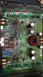
OK let me first start off by saying that I'm a NOOB to this site and to the internal workings of car audio amplification. Ive Been playing with Car Audio for 20+yrs now but never got into the internal workings and I'm very interested in learning. Ive been reading/Studying BCAE Basic amplifier repair tutorial over and over to suck up every last detail i can but as i said I'm very fresh to this Subject so please bear with me and what will probably be some dumb Questions. Okay so now on to my questions. I have a RF 250a2 that I've had since new in 99. The Right channel hasn't worked in years. The 2 output Transistors on the Right channel are dead. Zero Voltage on the center leg. (33V on the left outputs). I'm looking up parts to replace them and the Transistors say IRF540 and IRF9540 on them. when i look on Mouser.com there's a bunch of different options for the IRF540. Some Just say IRF540 but theres also 540PBF or 540NPBF, and also some other with letters following the IRF540 with the TO-220-3 case. They all seem to have the same 100V rating but some Have 28A and some are 33A or 36A options. Can i use any amp rating as long as there all matched? Are more Amps better or able to handle more load? I plan on replacing the Left side too so it will be as balanced/equal as possible . Also why are the 2 ouput transistors 2 different #'s IRF9540 and 540. Sorry for being so long But i do appreciate any Advice. Thanks in advance.
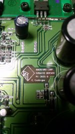
What's the PC board number?
For Rockford amps, the N version can cause problems. The 540PBF is OK.
The transistors are opposite polarity. One drives the output above 0v. The other drives the output below 0v.
In the future, break up the text. It makes it much easier to read.
For Rockford amps, the N version can cause problems. The 540PBF is OK.
The transistors are opposite polarity. One drives the output above 0v. The other drives the output below 0v.
In the future, break up the text. It makes it much easier to read.
It's not that it was too long. When there are no paragraph breaks or a break after a question, it's difficult (for me, maybe others) to get it all in one pass. For something like that, I may have to read it 4, 5, 10 times to get it all.
You should have 0v on the center legs of all output transistors.
You should have 0v on the center legs of all output transistors.
Yes.. I just tested again and got -31V on the 9540 and +31V on 540. I brought home my Fluke DVOM from work tonight to compare to my chepo craftsman at home and it was 2v less but.. Not sure why but i trust my Fluke over any other brand. Also i hooked up a speaker just for the heck of it and it has amazingly clean clear sound on that channel.
Also is there a particular brand that is more superior than one another. I see International and Vishay available in what i need. Someone told me that Fairchild is kind of a cheaper less than middle grade brand. Don't know how much truth there is in that but i Would like to have this amp last as long as i can.
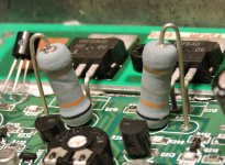
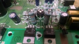
OK.. well even though i still dont see the burned source resistor ( sure your eye is better than mine) there is one odd or different reading. the 2 source resistors on the good channel read 000.5ohm .. the bad channel N channel fet resistor also reads 000.5ohm but the P channel resistor is all over the board but settled around 0.730k ohm. dont know what resistance is suppose to be but that one sure sticks out like a sore thumb.
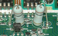
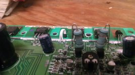
Ok so my next question would be how to I go about finding these resistors? I don't see a # or marking on it anywhere. If your schematic shows what they are would you mind sending It to screamin46@gmail.com. Thank you very much
- Status
- This old topic is closed. If you want to reopen this topic, contact a moderator using the "Report Post" button.
- Home
- General Interest
- Car Audio
- RF Punch 250a2 output Transistor?