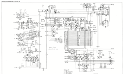
A friend brought me his Revox B286 preamp/tuner which powers up fine but has a very low level output. I discovered that fuses on the Line Amplifier card had blown. I replaced them, and all the dreaded Frako caps that Studer/Revox used. I could see input from all sources but no output at the first stage (IC 100/200). I discovered there was no clock data at IC 301 which I believe will step up the volume. Tracing to the Microprocessor board, there is no clock signal at MPU1 or MPU 2.
The DC voltage looks good coming into the chips. I have only repaired gear with discrete components, so this is new territory for me. I do see the crystal for obtaining the clock and believe it is good. I have recently replaced the 7705 reset generator chip (IC2) with no change.
Attached is a schematic. Any help in finding the system clock is greatly appreciated!
Attachments
Hi SteveF137,
I'm a Steve also. 😀
Why do you believe the crystal is good? It would be among my chief suspects.
The test equipment of choice would be a 'scope with x10 scope probe, and I hope that's how you confirmed absence of clock. It will allow you to observe any clock activity and also DC bias voltage at the XTAL2 processor pin. The x10 probe is necessary to minimize load capacitance.
On the Master processor, you should find DC bias on XTAL2 of roughly 2.5V, but what do you observe? Perform the same bias check on the Slave XTAL2 for comparison.
The observed bias will guide your troubleshooting. If you find around 2.5V, the processor's active stage is probably viable and you should suspect the crystal or its two shunt capacitors. The internal stage is inverting, so that will be a clue if you find XTAL2 is stuck at ground or +5V.
Let us know what you discover and we can offer advice if needed.
Good luck!
Steve
Hi Steve,
Thanks so much for your reply!
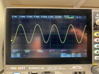
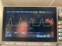
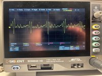
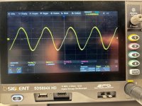
I while ago I measured the crystal and found the frequency output close to the 4.4336 MHz, so figured it was good. I'll send some pictures of my scope so you can observe my findings. This is with a 10x probe, DC coupled.
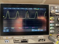
#1 Master XTAL2 (pin 16)
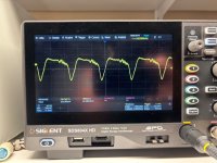
#2 Slave XTAL2 (pin 16)
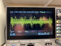
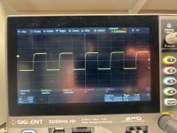
#3 Master SCLCK (pin 3)
So as you see the voltage at the Master is 2.49vdc RMS. The Slave is 2.21vdc RMS. The waveforms are dissimilar.
The Master CLK is very low level and for lack of better terminology...a bit of a mess.
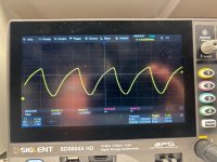
So you are aware, I also have a B252 preamp. It has the same MAB8440 chip (no slave) and the clock output of pin 3 looks more like you would expect. There is programming baked into these, so swapping is not possible...I believe.
I pulled both crystal shunt capacitors (C16, C17) and they measure 33pF.
Open to more thoughts.
Thanks again,
-Steve
Thanks so much for your reply!
I while ago I measured the crystal and found the frequency output close to the 4.4336 MHz, so figured it was good. I'll send some pictures of my scope so you can observe my findings. This is with a 10x probe, DC coupled.
#1 Master XTAL2 (pin 16)
#2 Slave XTAL2 (pin 16)
#3 Master SCLCK (pin 3)
So as you see the voltage at the Master is 2.49vdc RMS. The Slave is 2.21vdc RMS. The waveforms are dissimilar.
The Master CLK is very low level and for lack of better terminology...a bit of a mess.
So you are aware, I also have a B252 preamp. It has the same MAB8440 chip (no slave) and the clock output of pin 3 looks more like you would expect. There is programming baked into these, so swapping is not possible...I believe.
I pulled both crystal shunt capacitors (C16, C17) and they measure 33pF.
Open to more thoughts.
Thanks again,
-Steve
Attachments

I’m thinking the master looks clean because the crystal is a high Q resonator and acts as a filter.
Though the slave XTAL2 is distorted, is the amplitude similar? It’s possible the processor is being properly driven at 4.43 MHz. Can you find any other reasonable looking activity on any of the slave processor pins?
Though the slave XTAL2 is distorted, is the amplitude similar? It’s possible the processor is being properly driven at 4.43 MHz. Can you find any other reasonable looking activity on any of the slave processor pins?
Slightly off topic, are those custom ICs, or standard ICs (processors) with custom Revox programming? Can you read the program off of them? I have heard (zero experience) that the introduction of programmed logic chips/processors (?) in the three-digit Revoxes makes them much more difficult to fix than the older two-digit models; is that true? How often is it the custom logic/processor chips that go bad?

The Master CLK is very low level and for lack of better terminology...a bit of a mess.
What timebase did you have set for the SCLK scope image, I found the datasheet for the MPU's and it seems to specify the max SCLK frequency is 100KHz.
Try setting the timebase on the scope to say 100uS and see if the SCLK is visible.
Slightly off topic, are those custom ICs, or standard ICs (processors) with custom Revox programming?
Essentially standard type microcontrollers with an internal ROM which is masked programmed with the code from Revox by the manufacturer (Philips), so if it fails you need to find the exact same device from another Revox B286. The two MPU's have different part numbers so I'm assuming they have different ROMs.
Slightly off topic, are those custom ICs, or standard ICs (processors) with custom Revox programming? Can you read the program off of them?
The micros most probably have a mask rom, which you cannot read. The best you can do is make sure clock, reset an PS lines are as expected.
In the circuit above there are also eeproms external to the processors, which are certainly readable and more likely to be corrupted than the processors. This is perhaps the only realistic chance for an easy repair. And of course getting the processors as original spare parts.
These days programming microcontrollers is really easy. If the functions and protocols that need to be replicated are known, this entire control board can be replaced with one of the many modern alternatives. The effort and time could perhaps be recouped by offering boards for sale.
Great advice from everyone!
Slow time base way down and look for viable activity on both processors on any pin—- any indication of “intelligent” life on each processor.
I’m a little surprised that the XTAL2 pin on the slave isn’t a but more robust. You might inspect bias and waveforms on the transistor stage that drives XTAL1 of the slave. The drive is likely adequate, but worth a look.
Good luck!
Thank you all for your replies! Indeed the microprocessors have burned in instructions. The only replacement is a donor chip, thus I am trying to determine if the chips are still good given there is no usable clock.
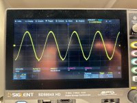
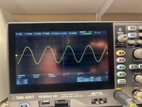
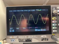
I have attached more pictures of my scope with descriptions of the MASTER and SLAVE pins. The MASTER CLCK Pin 3 is a single capture. Also base and collector of Q3 (thanks Steve). I have checked the capacitor (C10) that bridges this with XTAL 2 and it measures fine.
Lastly, my scope on the microprocessor pins of the working B 252.
Still hunting.
Attachments
-
 B 252 XTAL 1 Pin 15.jpg114 KB · Views: 37
 -
 B 252 CLCK Pin 3.jpg107.3 KB · Views: 29
 -
 Q3 collector.jpg113.7 KB · Views: 32
 -
 Q3 base.jpg105.3 KB · Views: 22
 -
 MPU 2 MASTER XTAL 2 pin 16.jpg107.1 KB · Views: 26
 -
 MPU 2 MASTER XTAL 1 pin 15.jpg99.2 KB · Views: 24
 -
 MPU 2 MASTER CLCK pin3 single.jpg115.6 KB · Views: 22
 -
 MPU 1 SLAVE XTAL 2 pin 16.jpg104 KB · Views: 19
 -
 MPU 1 SLAVE XTAL 1 pin 15.jpg104.3 KB · Views: 31
 -
 B 252 XTAL 2 Pin 16.jpg120.4 KB · Views: 24
- Home
- Amplifiers
- Solid State
- Revox B286 Preamp - No Volume Control