Hi everyone,
I try to repair my beloved Revox a78.
The right channel power transistors (2N3055, Q505 and 506, board 1.078.115 on the schematic) keep blowing when I power the amp.
The main fuse is too strong, it doesn't blow.
100 ohm R511 or 512 catch fire...
I measured every pin of both power amp board sockets and every voltage or resistance is close to ideal value.
I tried switching the boards, and it always blows on the right channel.
If you have any idea, or general advice in methodology it would be greatly appreciated.
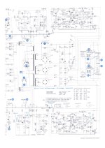
Schematic is attached to this post.
Thanks for reading!
Paul
I try to repair my beloved Revox a78.
The right channel power transistors (2N3055, Q505 and 506, board 1.078.115 on the schematic) keep blowing when I power the amp.
The main fuse is too strong, it doesn't blow.
100 ohm R511 or 512 catch fire...
I measured every pin of both power amp board sockets and every voltage or resistance is close to ideal value.
I tried switching the boards, and it always blows on the right channel.
If you have any idea, or general advice in methodology it would be greatly appreciated.
Schematic is attached to this post.
Thanks for reading!
Paul
Attachments

The power amp looks conventional enough but I'm a bit concerned over the 2N3055's and the -/+41 volt rails. I wonder if the originals were selected devices as the 2N3055 I know only has a 60 volt Vce rating from memory meaning its only good for supplies of around -/+25 volt to avoid the risk of secondary breakdown.
I think you will find that the driver transistors are likely damaged. Good outputs, good drivers, it should work. I would short the base of the drivers together for testing to force zero bias current. Do that and if the outputs and drivers are good then it can not draw fault current via the output stage (but will still work as an amp OK for testing). The only exception to that is if there is a short on the output line.
You also need to check ALL the low value resistors in the output stage such as the three 1 ohm resistors and the 0.47 ohm. Also check (replace) the three IN4001 diodes in that area.
Using a bulb tester is a good idea to prevent further blow ups and damage.
You need (imo) to look at something better than a standard 2N3055 as they are not suitable for that supply voltage. I think the originals will be a special high voltage version.
Hi Paul, welcome.
You have some basic measurement gear (multimeter) and skills?
You will want to check Q503 / Q504 which will most likely be bad if R511 / R512 fail.
Also check Q506 / Q507 and all surrouding diodes.
Emitter resistors R514 & R 516 with the two diodes attached also need checking.
For starters 🙂
Oops Mooly, you posted while I wrote...
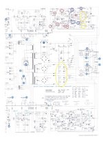
I have successfully repaired couple of those very old but very good sounding Revox A78 amp. , notice that it is mandatory to replace all those for sure dried and bad electrolytic caps circled in red , altogether with two trim-pots , those two driver transistor Q503/Q504 you can replace with Japan made 2SD669AC/2SB649AC , also check all those passive elements circled in yellow , and notice that those power amps works with virtual ground achieved via four power resistors , R903/R904 , and R923/R924 ., notice on PCB that there`s no polarization marks for electrolytic capacitors , so before you de-solder those caps make some your own marks on PCB surface for latter correct orientation and polarization , and yes , those PCB copper tracks and lines are very thin and need special care by soldering process .