Have a set of Kef X300A of which one has become noisy. Replaced the capacitors in the power supply, seemed to solve it, but the static noise came back overnight. Have included a clip of the noise recording, I believe this indicates a faulty transistor?
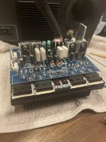
I have now removed the AB amplifier from the speaker and found many transistors on the board. It’s a two channel amplifier that bi-amps the Kef coaxial driver.
The board consists of:
2x 2SC5200/2SA1943
2x 2SC3421
2x 2SA1930/2SC5171
2x 2SC2229
4x 2SA949
It would be quite cost and time intensive to replace them all. Is there a way to go about this?
Clip of the noise:
Attachments

Last edited:
Yes, trace which one or rather where the noise is coming from, a can of freezer spray can help to pin point the noisy component.
Example; https://uk.rs-online.com/web/c/?searchTerm=freezer+spray
Don't throw parts at it! Find and then fix the fault.
Example; https://uk.rs-online.com/web/c/?searchTerm=freezer+spray
Don't throw parts at it! Find and then fix the fault.
Just what I was going to say - mechanical or thermal disturbance may identify which device or solder joint is responsible. When you replaced the caps the mechanical disturbance may have caused the temporary improvement.
Do not look for a faulty transistor, more likely you have a bad solder join.
The pics show a lot of rework, I will suggest to remove the excess of solder and solder again with fresh solder.
Please look at the back of the board and re-solder the pins of the headers, they are the most common fault I found on old equipment.
The pics show a lot of rework, I will suggest to remove the excess of solder and solder again with fresh solder.
Please look at the back of the board and re-solder the pins of the headers, they are the most common fault I found on old equipment.
Just resoldered all transistor pins and suspicious looking joints. Didn’t seem to work. Will try to move some components from te working speaker and see if that solves it.
please check the header's pins first, what I found in old equipment (much older than yours) was a thin layer of oxide around the pins which created the intermittent contact (an inspection with a glass magnifier should help).
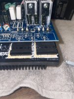
I would agree with anibal. The solder joints on the 2SC5200/2SA1943 look pretty bad, as do the smaller pair of devices attached to the heatsink. I would use a solder sucker and remove all old solder from any suspect joint and resolder with leaded 60/40 or 63/37 solder. This looks like lead free solder and the joints look cold, not shiny, with too much solder.
Another clip of the noise. Here you can also notice the intermittentness, sometimes it works fine sometimes it doesn’t. There is also less body to the sound when playing music, it sounds thinner and higher pitched.
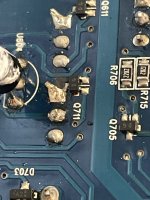
Other than the solder joints looking a bit dodgy, that apparent solder bridge between Q711 and Q710 is actually right on top of a trace. Those nodes are supposed to be connected! From the Dead KEF X300A thread you seem to have isolated the problem to the one amplifier. The intermittency is of the problem is clear in the videos...I suspect the solder joint at Q711 to be at fault. Attached a screenshot. What do you think?
Your sound/video samples are intriguing (and distressing). It might be illustrative (if you can stand it) to post what the speaker sounds like with signal. Something simple in which there should be recognizable highs and lows, like a small Jazz combo - or a small illustrative collection of sinusoids. Mind your ears!
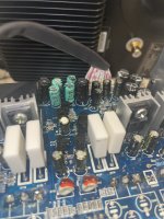
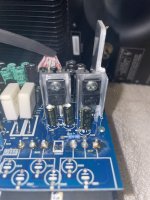
I'm assuming you've done a sanity check on the main +/- power supply rails on the amp board? There's also a set of lower voltage rails to feed the input op amp (provided by the regulators visible in IMG_0909, above) that should also be stable. Another quick sanity check would be the voltages across the big, white output emitter resistors in IMG_0907 and IMG_0908. Those should probably be in the 10 to 20mV range with no signal (i.e. not zero, and not 100mV or more!). Do you happen to have access to an oscilloscope, to probe a test signal at various points on the board?
- Home
- Amplifiers
- Solid State
- Revive my active KEFs